



Removal
1. Mark the position of the front wheels on the hubs with paint. This will allow the balanced wheel to be returned to its original position during assembly.
2. Loosen the wheel mounting bolts. In this case, the car must stand on its wheels.
3. Remove cotter pin 1 and cap 2, which secure hub nut 3 (see illustration).
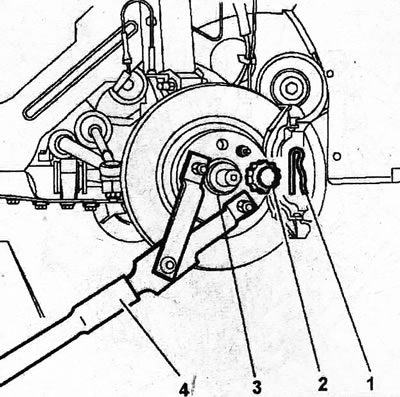
5.3. Remove cotter pin 1 and cap 2, which secure hub nut 3
4. Lock the hub from turning with stop 4 and unscrew its nut 3 (see illustration 5.3).
Caution! It is recommended to hold the hub with a stop. When using the brake, it is possible that the brake disc mounting bolts may be damaged due to the significant tightening torque of the hub nut.
5. Place the front of the car on stands, unscrew the wheel bolts and remove the front wheel.
6. Unscrew nut 3 of the clamp bolt of the ball joint pin of the lower wishbone to the steering knuckle and remove the bolt (see illustration).
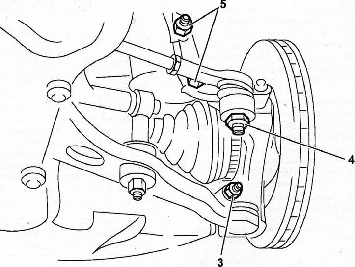
5.6. Unscrew nut 3 of the clamp bolt of the ball joint pin of the lower wishbone to the steering knuckle and remove the bolt
7. Unscrew the nut 4 of the ball joint pin of the tie rod end and press the pin out of the steering knuckle arm (see illustration 5.6).
8. Unscrew the caliper mounting bolts, remove it by pushing it upwards, and then secure it with wire to the body, without allowing the brake hose to stretch.
Caution! Do not disconnect the brake hose from the caliper. Otherwise, you will have to bleed the brake system later. Attach the caliper so that it does not hang on the brake hose and does not stretch it with its weight.
9. Unscrew the mounting bolts and remove the brake disc from the hub.
10. Unscrew nuts 5 of both bolts securing the lower part of the shock absorber strut to the steering knuckle (see illustration 5.6).
11. Tie the drive shaft to the body or support it with an appropriate support. This is necessary to ensure that after the shaft is disconnected from the hub and steering knuckle, it does not sag.
12. Turn the steering knuckle to the side and disconnect the drive shaft, and also remove the lower part of the shock absorber from the clamp on the knuckle.
Caution! It is not permitted to install the vehicle on wheels with one or two drive shafts removed. This will cause damage to the wheel bearings. If it is necessary to install the vehicle on its wheels and move it after removing and disassembling the drive shafts, then instead of the shaft, install the tailpiece of its outer joint into the hub, screw on the hub nut and tighten it.
13. Disconnect ABS sensor 7 (see illustration).
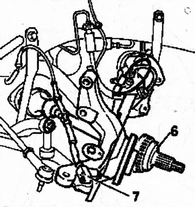
5.13. Disconnect ABS sensor 7 6 - drive shaft
The steering knuckle is installed in the reverse order of removal.
14. Replace with new self-locking nuts and bolts. Apply protective grease to the threads of the caliper mounting bolts to prevent the bolts from loosening.