



Caution! The procedure for removing and installing the modulator requires strict adherence to cleanliness and accuracy.
Cars with BVA AL4 automatic transmission
Removal
1. Disconnect the negative (-) battery terminal and support the front of the vehicle on stands.
2. Place a container under the vehicle to drain the transmission fluid from the modulator. The volume of liquid drained is approximately 1.5 liters.
3. Unscrew bolts 1 securing cover 2 of the gearbox and remove the cover (see illustration).
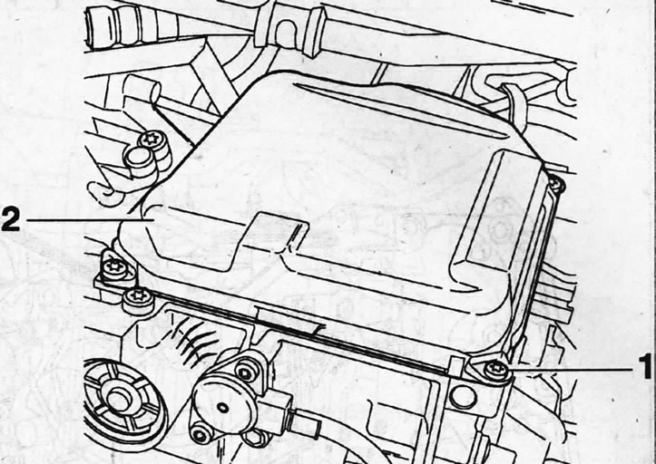
5.3. Unscrew bolts 1 securing cover 2 of the gearbox and remove the cover
4. Disconnect the plugs of the six electromagnetic valves by prying them with a screwdriver, and then disconnect the valves themselves by unscrewing their mounting bolts, the tightening torque of which is 10 Nm (see illustration).
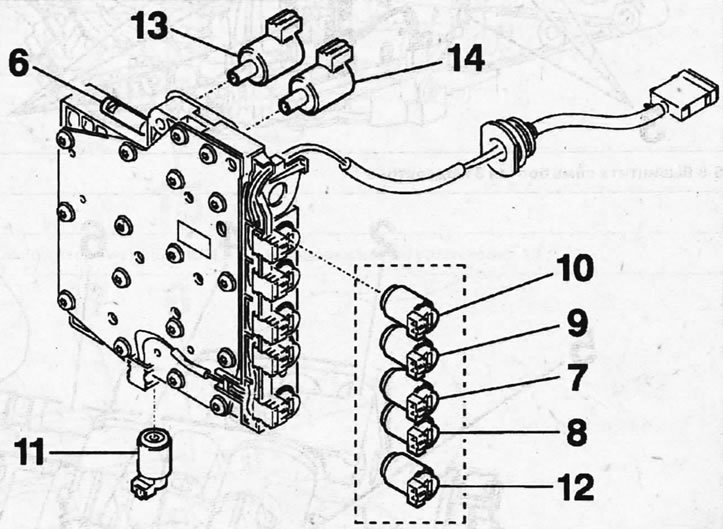
5.4 Modulator valves 6 - manual gear shift mode valve; 7-12 - automatic gear shift electromagnetic valves; 13 - electromagnetic discharge valve; 14 - electromagnetic pressure reducing valve
Caution! When disconnecting valve 11, do not allow the hydraulic valve located underneath to fall out.
After disconnecting the electromagnetic valves, their seals must be replaced with new ones.
5. Unscrew the seven bolts 3 of the modulator (see illustration).
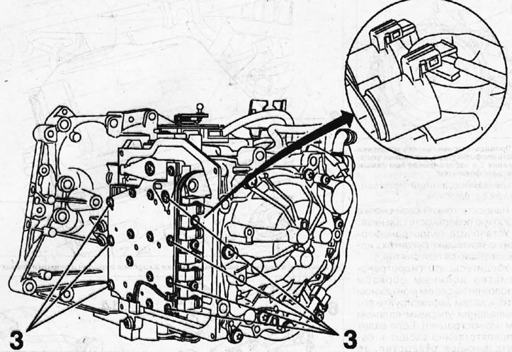
5.5. Unscrew the seven bolts 3 of the modulator
6. Move modulator 2 from its seat and disconnect valves 4 and 5 located on its rear side, as well as valve 6 for manual gear shifting mode (see illustration).
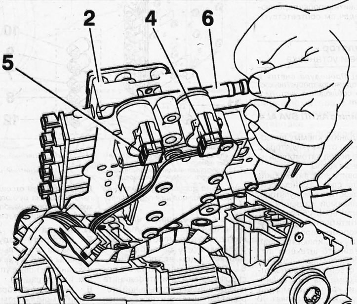
5.6. Move modulator 2 from its seat and disconnect valves 4 and 5 located on its rear side, as well as valve 6 of the manual gear shift mode
Caution! When disconnecting manual transmission mode valve 6, do not apply excessive force to it.
Installation
7. Assemble the modulator by attaching valves 4 and 5, as well as valve 6, to its rear side and installing new seals 15 (see illustration).
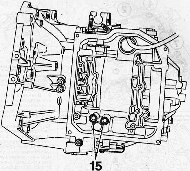
5.7. Assemble the modulator by attaching valves 4 and 5 to its rear side and installing new seals 15
8. Install the assembled modulator on the mounting location, properly aligning protrusions 17 and 16 (see illustration)
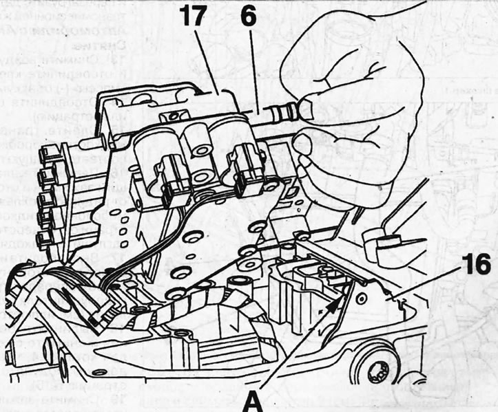
5.8. Install the assembled modulator on the mounting location, properly aligning protrusions 17 and 16
Attention! When installing the modulator, valve 6 must fit into recess A on protrusion 16 with notches (see illustration 5.8).
9. Screw in the modulator mounting bolts and tighten them to 8 Nm, acting in ascending order of their numbering (see illustration).
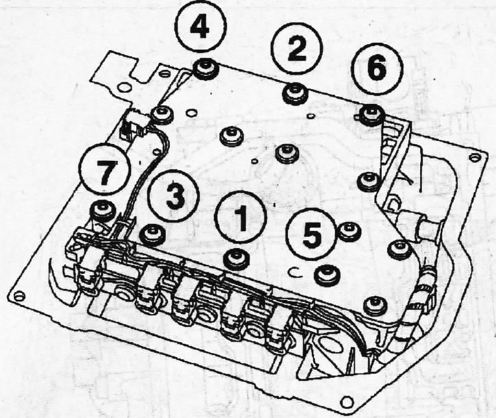
5.9. Screw in the modulator mounting bolts and tighten them with a force of 8 Nm, acting in the sequence of increasing their numbering
10. Connect the remaining six solenoids.
11. Make sure that the gearbox control lever moves freely in all positions and install the gearbox cover, replacing its old sealing gasket with a new one. The tightening torque of the cover bolts is 10 Nm.
12. Top up the transmission fluid, see the relevant chapter and reset the transmission fluid condition sensor.
Vehicles with 4HP20 AT
Removal
13. Remove the air filter and disconnect the negative (-) battery terminal.
14. Disconnect plug 1 (see illustration).
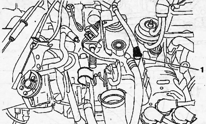
5.14. Disconnect plug 1
15. Drain the transmission fluid from the gearbox, see the relevant chapter.
16. Clamp hose 2 with a suitable clamp and disconnect it from the transmission fluid cooling radiator (see illustration). Plug the radiator hole with a suitable plug.
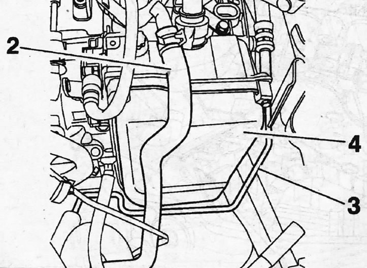
5.16. Clamp hose 2 with a suitable clamp and disconnect it from the transmission fluid cooling radiator
17. Release the power steering line 3 from the holder and move it away from the gearbox cover 4 (see illustration 5.16).
18. Unscrew the mounting bolts and remove cover 4 from the gearbox to gain access to the modulator (see illustration 5.16).
19. Remove clamp 5, which holds the hose on the branch pipe (see illustration).
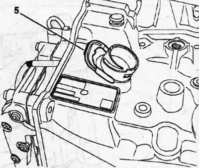
5.19. Remove clamp 5, which holds the hose on the branch pipe
20. First loosen the tightening and then unscrew the 6 bolts securing the modulator (see illustration).
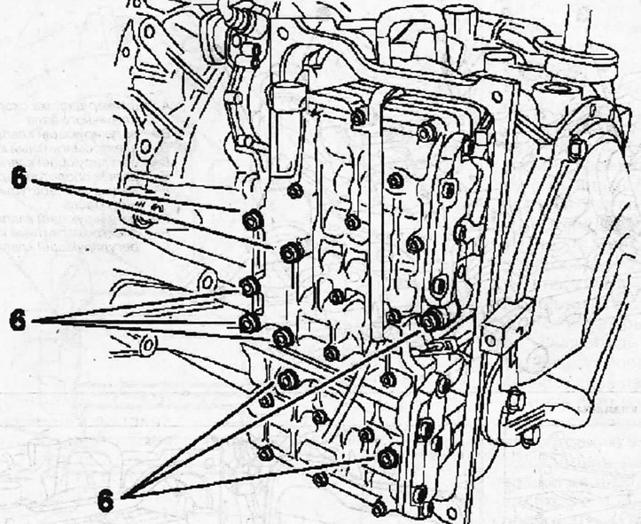
5.20. First loosen the tightening and then unscrew the 6 bolts securing the modulator
21. Disconnect the speedometer sensor 7 and the connector 8 of the input shaft speed sensor and remove the modulator 9 (see illustration).
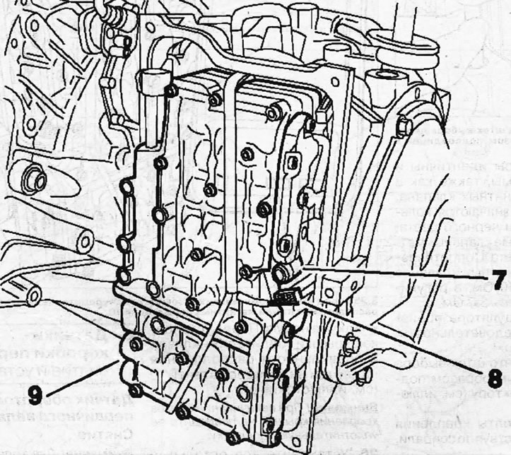
5.21. Disconnect the speedometer sensor 7 and the plug 8 of the input shaft speed sensor and remove the modulator 9
22. Disconnect connector A of the secondary shaft speed sensor (see illustration).
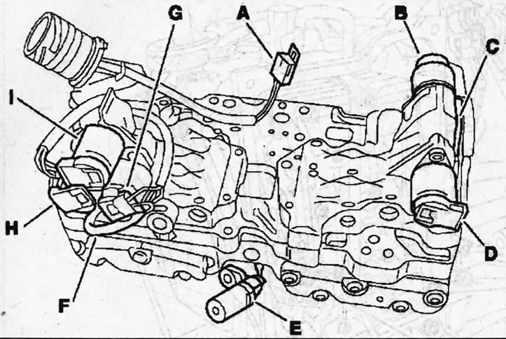
5.22. Modulator and its valves A - secondary shaft speed sensor plug; B - control valve No. 6; C - electromagnetic valve MV1; D - control valve No. 4; E - primary shaft speed sensor; F - transmission oil temperature sensor; G - control valve No. 3; H - electromagnetic valve MV2; I - control valve No. 5
Caution! Before removing valves and regulators from the modulator, mark their mounting position.
All regulators are identical and interchangeable, as are both solenoid valves. Regulators are marked with black ring marks, solenoid valves - with yellow marks. The resistance of electromagnetic valves is 30-40 Ohm, and control valves - 3-7 Ohm.
The modulator is installed in the reverse order of removal.
23. Make sure that the gear selector shaft is properly connected to the selector (see illustration).
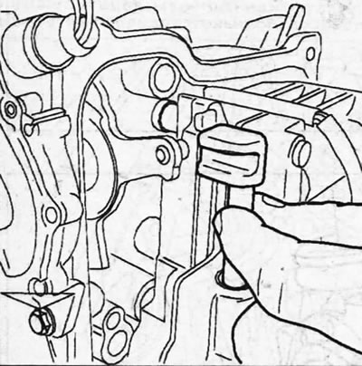
5.23. Make sure that the gear selector shaft is properly connected to the selector
24. Tighten the modulator mounting bolts in a spiral pattern to 8 Nm.
25. Reinstall the gearbox cover, replacing its old sealing gasket with a new one. Before installing the cover, make sure that the magnetic holders are present and correctly positioned on it 10 (see illustration).
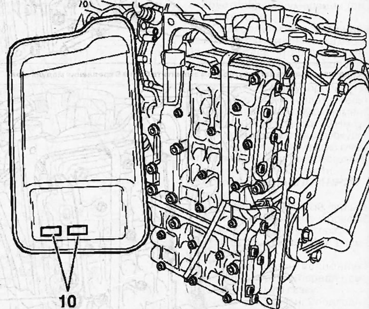
5.25. Before installing the gearbox cover, make sure that the magnetic holders 10 are present and correctly positioned on it
Caution! When tightening the cover mounting bolts, be careful not to damage the cover sealing gasket.
Material copied from the resource: PeugeotBook
26. Install all remaining components and fill with transmission fluid, and if drained, coolant.