



Table of contents: Removal 🠇 Installation 🠇
Removal
1. Removing the gearbox cover is shown using the ML5C gearbox as an example. It is recommended to mark the mounting positions of the parts being removed so that the marks can be used as a guide during reassembly.
2. Unscrew bolts 1 that secure the rear cover 2, which covers the gear and the 5th gear shift fork, and remove it together with the sealing gasket (see illustration).
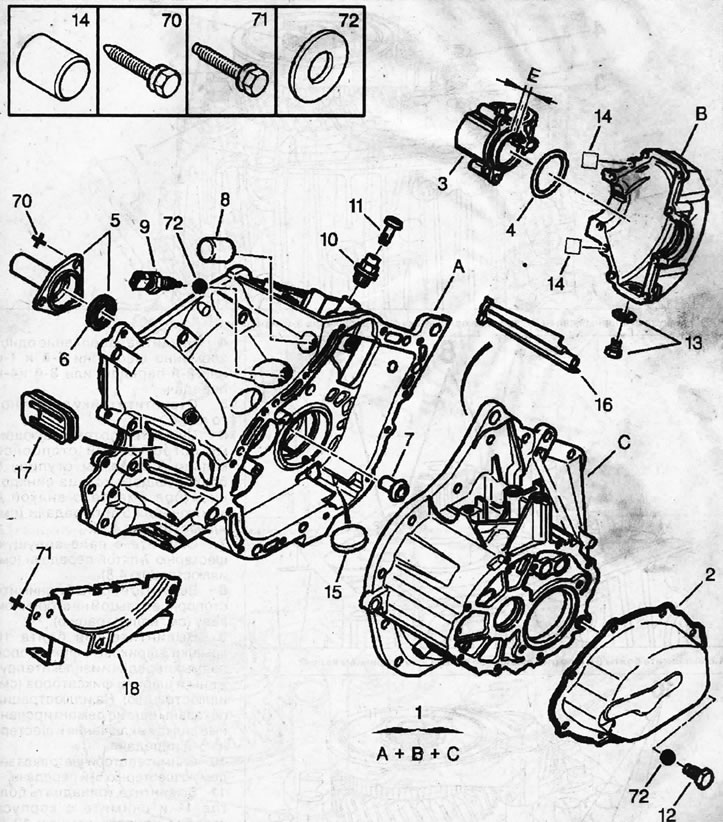
4.0. Housing A and cover C of the BE4/5 gearbox A+B+C (gearbox housing + differential + cover); 2 - rear cover of the gearbox; 3 - shaft extension; 4 - oil seal; 5 - primary shaft guide sleeve; 6 - primary shaft seal; 7 - oil nipple; 8 - cork; 9 - Reverse light switch; 10 - gearbox ventilation valve; 11 - cork; 12 - filler plug; 13 - differential housing hole plug; 14 - centering pins and their location; 15 - magnet; 16 - filling hole tube; 17 - corrugated membrane; 18 - bracket; 70 - self-locking bolts M7X100-18; 71 - self-locking bolts M8x125-16; 72 - sealing ring for threaded plugs
3. Remove the locking pin 3 holding the 5th gear shift fork 4 and remove the fork (see illustration).
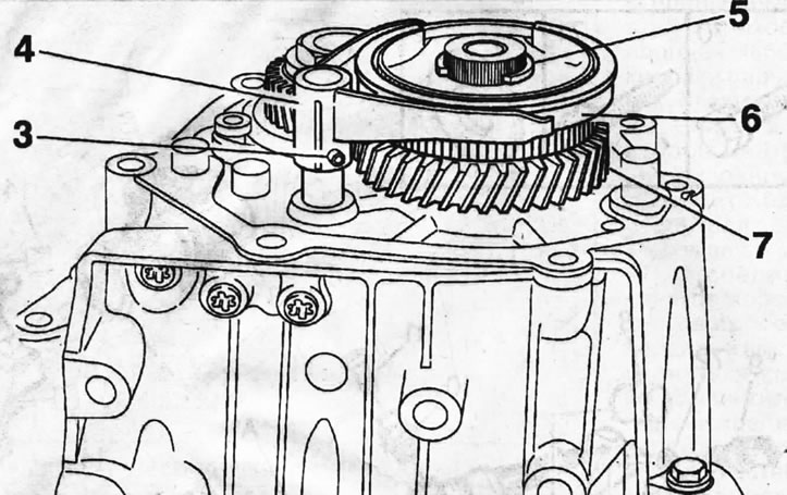
4.3. Remove the locking pin 3 holding the 5th gear shift fork 4
4. Engage the 5th and 1st or 2nd gears, or 3rd and 4th gears simultaneously.
5. Unscrew the secondary shaft nut.
6. Using appropriate pliers, remove the retaining ring 5, and then the hub 6 of the synchronizer locking ring together with the fork 4 for disengaging the 5th gear (see illustration 4.3).
7. Remove the fifth gear pinion 7 from the shaft (see illustration 4.3).
8. Unscrew bolts 8 and remove retaining ring 9 on the secondary shaft (see illustration).
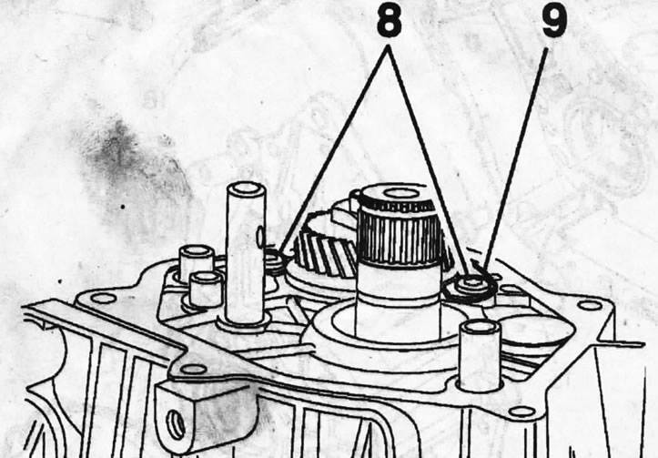
4.8. Unscrew bolts 8 and remove retaining ring 9 on the secondary shaft
9. Unscrew the three bolts 10 of the direct drive ball locking cover and remove the springs and locking balls (see illustration). The illustration shows the release fork and 5th gear gear not yet removed.
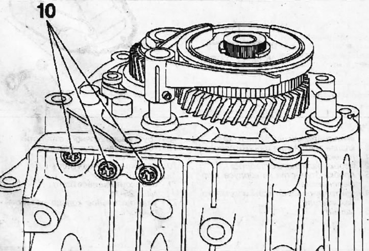
4.9. Unscrew the three bolts 10 of the direct drive ball locking cover and remove the springs and locking balls
10. Remove the 5th gear driven gear from the secondary shaft.
11. Unscrew the thirteen bolts 11 and remove the cover 12 from the gearbox housing, as well as the disk-shaped magnet (see illustrations 4.11 and 4.0).
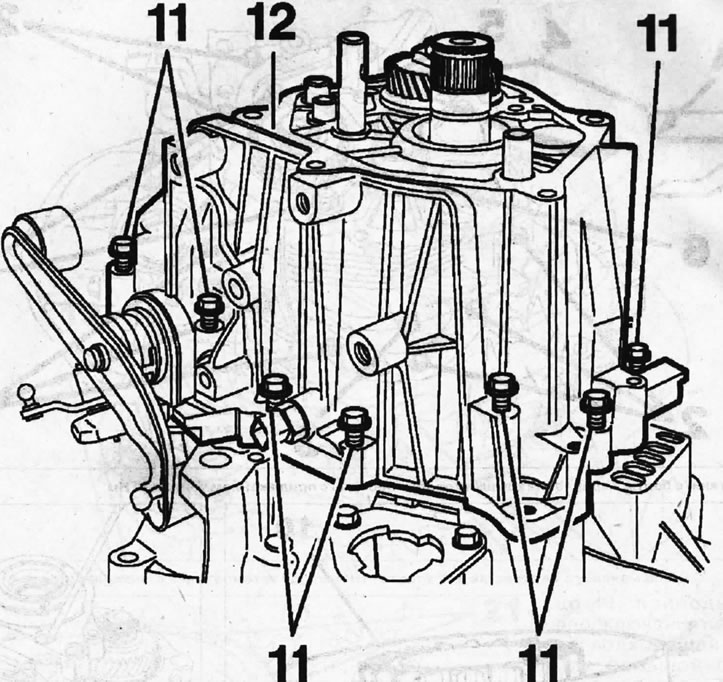
4.11. Unscrew thirteen bolts 11 and remove cover 12 from the gearbox housing
Installation
Gearbox BE4/5
12. Install the gearbox cover onto the housing and make sure that the cover hole is aligned with the oil tube 1 for filling the transmission fluid (see illustration).
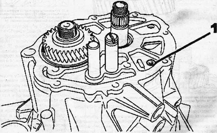
4.12. Install the gearbox cover onto the housing and make sure that the cover opening is aligned with the oil pipe 1 for filling the transmission fluid. Gearbox BE4/5
13. Screw in and tighten the 2 gearbox cover mounting bolts with a force of 15 Nm (see illustration).
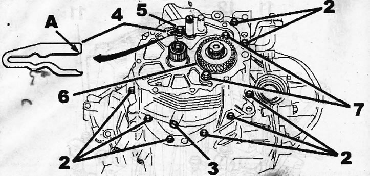
4.13. Screw in and tighten the 2 gearbox cover mounting bolts with a force of 15 Nm
14. Screw plug 3 with a new gasket into the transmission fluid level check hole and tighten it to 20 Nm (see illustration 4.13).
15. Install the fork-type plate 4 by inserting its flattening A into the groove on the shaft (see illustration 4.13).
16. Tighten bolt 5 with a force of 15 Nm, install driven gear 6 of fifth gear on the secondary shaft and screw in bolts 7, tightening them with a force of 15 Nm (see illustration 4.13).
17. Place the spacer 8 and thrust 9 gaskets on the primary shaft, as well as the fifth gear gear 10 (see illustration).
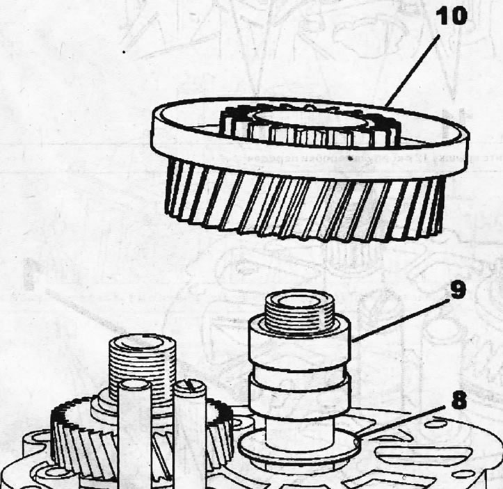
4.17. Place the spacer 8 and thrust 9 gaskets on the primary shaft, as well as the fifth gear gear 10
18. Install the hub 11 of the clutch and the locking ring 12 of the synchronizer together with the gear shift fork 13, pressing on the locking ball 14 and engage the gears (see illustration).
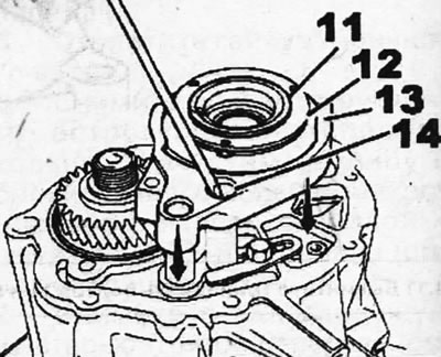
4.18. Install the clutch hub 11 and the synchronizer locking ring 12 together with the gear shift fork 13, pressing on the locking ball 14
19. Apply E6 sealant to the secondary shaft thread, screw on nut 15, tighten it to 65 Nm and secure it with a metal plate by inserting it into the groove on the shaft (see illustration).
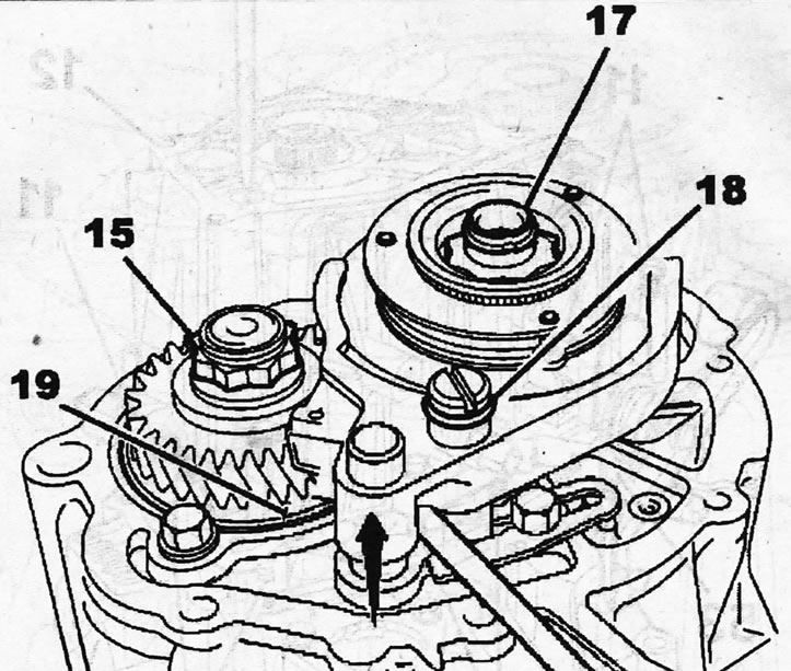
4.19. Apply E6 sealant to the secondary shaft threads, screw on nut 15 and tighten it to 65 Nm
20 Screw a new nut 17 onto the primary shaft, lubricating its threads with E6 sealant, and tighten the nut with a socket head applying a force of 72 Nm (see illustration 4.19).
Attention! Also lock the nut on the input shaft.
21. Install the locking ring 18, lift the gear shift fork by pressing it with a suitable pry bar or a large screwdriver until its hole is aligned with the hole on its mounting rod, and then lock the gear shift fork on the rod with a new pin 19 (see illustration 4.19).
22. Apply E15 sealant to the mating surface of the rear cover, place it in the mounting location, screw in plug 20 until its head is seated, and then screw in and tighten bolts 21 with a force of 15 Nm (see illustration).
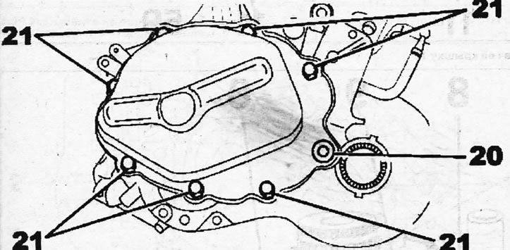
4.22. Apply E15 sealant to the mating surface of the rear cover, place it in the mounting location, screw in plug 20 until its head is seated, and then screw in and tighten bolts 21 with a force of 15 Nm
23. Tighten plug 20 with a torque of 20 Nm (see illustration 4.22).
ML5C gearbox
24. Install tube 13 for filling transmission fluid on the gearbox housing, lubricating the connecting surfaces with a thin layer of sealant EYU (see illustration).
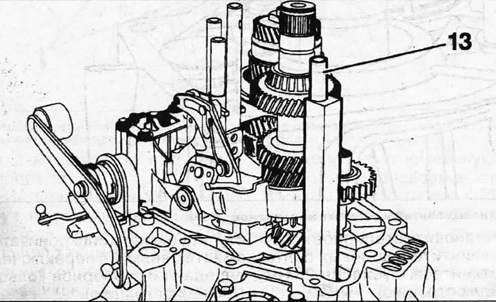
4.24. Install tube 13 on the gearbox housing for filling transmission fluid
25. Install the cover 12 on the gearbox housing 59, aligning the tube 13 with the corresponding hole on the cover with a screwdriver and screwing in the bolts 11 (see illustration).
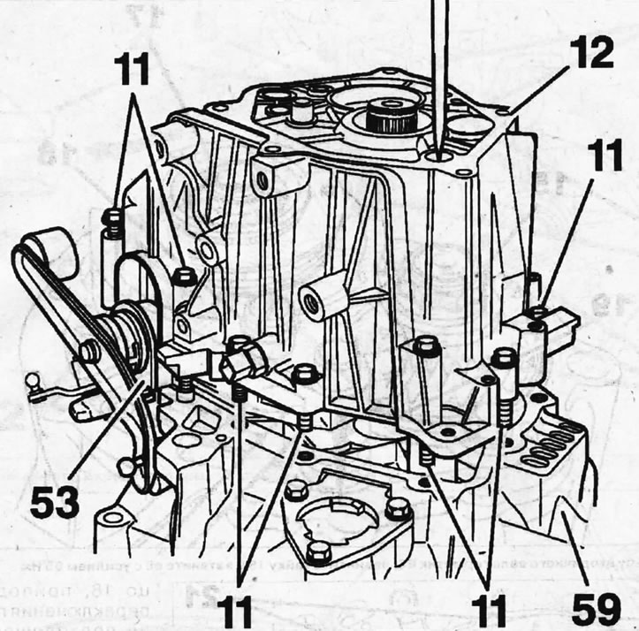
4.25. Install the gearbox cover 12 on the housing 59
[Original is contained on the portal: peugeotbook.ru]
26. Press the oil seal 53 of the gear selection and shift rod into place, avoiding bending of its edges (see illustration 4.25).
27. Tighten bolts 11 securing the cover to the gearbox body with a torque of 20 Nm (see illustration 4.25).
28. Install the retaining ring 9, screw in two new bolts 8 and tighten them to 25 Nm (see illustration).
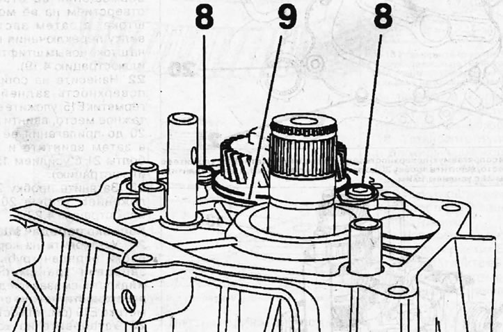
4.28. Install the retaining ring 9, screw in two new bolts 8 and tighten them to 25 Nm
29. Install the fifth gear pinion, hub 6 of the synchronizer clutch together with the gear shift fork 4 and retaining ring 5 on the primary shaft (see illustration).
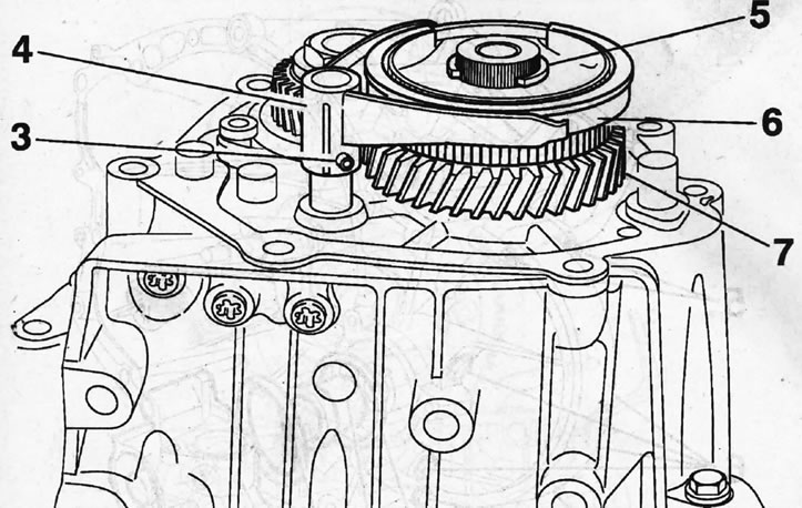
4.29. Install fifth gear pinion 7, synchronizer clutch hub 6 together with gear shift fork 4 and retaining ring 5 on the primary shaft
30. Engage the 5th and 1st or 2nd gears, or 3rd and 4th gears simultaneously.
31. Tighten the nut on the secondary shaft with a torque of 170 Nm and disengage the gears, thus engaging neutral gear.
32. Secure the 5th gear shift fork with pin 3 and place the sealing gasket on the filler hole (see illustration 4.29).
33. Apply E10 sealant to the sealing surface of the rear cover 2, place it on the seat, screw in and tighten the bolts 1 with a force of 20 Nm (see illustration).
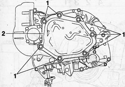
4.33. Apply E10 sealant to the sealing surface of the rear cover 2, place it on the seat, screw in and tighten the bolts 1 with a force of 20 Nm