



The master brake cylinder has a tandem design and ensures the operation of two brake circuits. The rear cylinder circuit controls the upper pistons of the disc brakes and the rear wheel brakes. The front cylinder circuit provides operation of the lower pistons of the disc brakes. On cars, various main brake cylinders become clogged. Figure 167 shows a diagram of the interaction of the brake system elements. A hydraulic brake booster is installed. The working vacuum on gasoline engines comes from the intake manifold. In diesel and turbodiesel engines, the required vacuum is created by a vacuum pump. Vacuum pumps from various manufacturers are installed on cars. The brake force regulator regulates the braking force of the rear wheels.
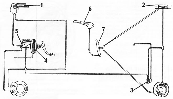
Figure 167. Brake circuit diagram.1. Front disc brakes; 2. Rear drum brakes; 3. Brake force regulator; 4. Hydraulic brake booster; 5. Master brake cylinder; 6. Handbrake lever; 7. Handbrake cable equalizer lever
The handbrake acts through cables on the rear wheels. Full handbrake effectiveness is achieved by tightening the handbrake lever 4 to 5 clicks.