



Table of contents: 13.3.1. Removing brake pads 🠇 13.3.2. Installing brake pads 🠇 13.3.3. Wheel brake cylinder 🠇
All cars are equipped with Girling brakes.
13.3.1. Removing brake pads
- Loosen the wheel nuts.
- Place the rear of the car on stands and remove the rear wheels.
- Remove the brake drum and wheel hub. The brake drum is fitted with a mounting bolt and a guide pin. To remove the brake drum from the hub, unscrew them (see Figure 174). However, since the brake drum sits on the hub quite tightly, it needs to be pulled off the hub. To do this, screw three M10x1.25 bolts into the three holes "a". The drum will come off the hub when these bolts are tightened evenly. If the drum cannot be removed, it is necessary to release the brake shoe installation mechanism from the inside of the drum. To do this, pull the handbrake and press the plug (1) in Figure 175 to move the mechanism inward. Pull out the plastic sleeve (2) to release the handbrake lever stop inside. Release the handbrake and pull off the brake drum.
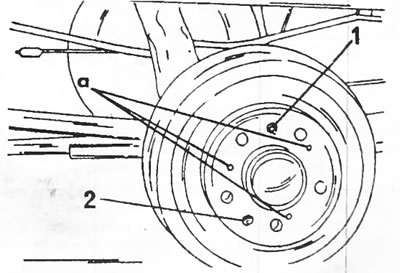
Figure 174. Removing the brake drum. You should unscrew the bolt (1) and pin (2). After this, screw the bolts into the holes "a".
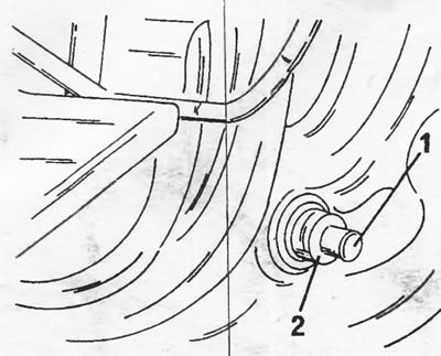
Figure 175. Releasing a tightly stuck brake drum. Press in the plug (1) and pull out the plastic sleeve (2). The handbrake must be applied.
- Using Figure 176, disconnect the adjusting lever (1) and the return spring (2). The upper return spring (4) and the lower spring (3) are disconnected with special pliers, but you can also hook the spring with a screwdriver. This releases the mounting strip (5), which can be removed.
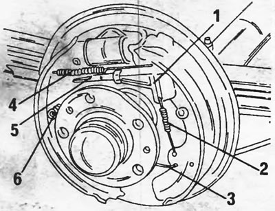
Figure 176. Rear wheel brake. 1. Setting lever; 2. Return spring of the installation mechanism; 3. Lower return spring; 4. Upper return spring; 5. Mounting plate; 6. Brake pad support pins
- Remove the support pins shown in Figure 177 from both brake pads. Usually this requires a special tool, but you can do without pasatizhami. At the same time, press your finger from the back side of the brake shield onto the head of the pin, and from the front side, grab the spring cup with pliers. Rotate the spring cup so that the pin head can be released from the spring cup retainer. Remove the cup and spring and pull the pin out from the back.
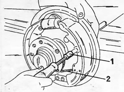
Figure 177. Removing the brake shoe support pins using a special tool (1). The handbrake cable is connected to the rear brake shoe lever.
- Do the same work with the second brake pad.
- Remove the brake pads and disconnect the handbrake cable from the rear brake shoe lever.
- If necessary, you can unscrew the wheel brake cylinder from the brake shield after disconnecting the brake pipe.
Thoroughly clean all parts, including the brake shield. If the parts are washed with gasoline, it should not come into contact with the rubber caps of the wheel brake cylinder. If the thickness of the brake pad linings is less than 2.0 mm, the pads are replaced. Brake pads can be replaced separately, but this is not recommended. If the wheel brake cylinder shows signs of leakage, it should be replaced or, if sufficiently experienced, repaired. In the latter case, it is necessary to purchase a brake cylinder repair kit.
13.3.2. Installing brake pads
- Screw the wheel brake cylinder onto the brake shield and connect the brake pipe from the rear of the brake shield.
- Place the brake pads on the brake shield and connect the handbrake cable to the lever.
- Insert the brake shoe support pins into the brake shield and place the spring and cup on the front. While holding the support pin from behind with your finger, grab the spring cup with pliers and push it onto the pin. When the pin enters the hole, turn the spring cup to fix it on the pin.
- Insert the mounting plate from the top side between the brake pads.
- Connect the upper and lower brake shoe return springs. To do this, attach the spring hook on one side and stretch the spring with pliers so that the second spring hook can enter the hole on the other side. Installation of springs is made easier by using special spring installation pliers.
- The following works are performed using Figure 178.
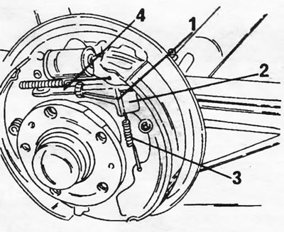
Figure 178. Installing brake pads. 1. Fastening the installation lever; 2. Setting lever; 3. Return spring; 4. Mounting plate
- Connect spring 93) to the brake shoe and to the upper side of the adjusting lever (1).
- Install the adjusting lever (1). In this case, end "a" in Figure 179 is placed under the rod (2), and the lever on the pin (3).
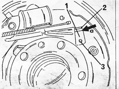
Figure 179. When installing the installation lever, place its end "a" under the rod (2).
- Center the brake pads on the brake shield.
- Install the brake drum and secure it with the bolt and rear wheel guide pin.
- To initially adjust the setting mechanism and install the brake pads, tighten the handbrake several times and press the brake pedal.
- If the wheel brake cylinder was removed, that is, the brake pipe was unscrewed, it is necessary to remove air from the brake system, as described in section 13.6. Each brake caliper has two air bleed valves.
- Put the wheels on and lower the car. Tighten the wheel bolts to the specified torque.
13.3.3. Wheel brake cylinder
Before replacing a wheel brake cylinder, you must purchase a repair kit. When repairing a wheel brake cylinder, it is necessary to have a certain amount of experience, since in addition to relatively simple disassembly, knowledge is required in determining the degree of wear. Otherwise, the only option left is to install a new brake cylinder. When disassembling the wheel brake cylinder, remove the wire ties from both rubber caps and carefully remove one rubber cap. In this case, the piston, which is under pressure, may come out. Remove the piston and spring, remove the rubber cap on the other side and remove the second piston. The disassembled cylinder is shown in Figure 180. Remove the rubber seals from both pistons. To tighten the cuffs, you can use a small screwdriver, but only to pry the cuffs and continue tightening it with your fingers. Before removing, pay attention to the installation position of the cuff.
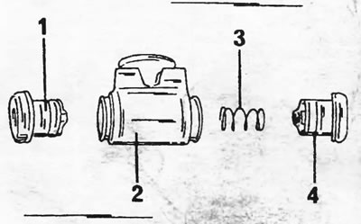
Figure 180. Disassembled wheel brake cylinder. 1. Piston and rubber cap; 2. Cylinder body; 3. Return spring; 4. Piston and rubber cap
Clean all parts thoroughly (do not use gasoline). Check the cylinder bore for wear and scratches. As a last resort, minor irregularities can be smoothed out with sandpaper.
Before assembly, lubricate all parts with clean brake fluid. Place new seals on the pistons with the sharp edges facing inward. Put on the cuffs without using any tools.
Insert the piston with the dust cover into the cylinder and put on the cap. On the other side, insert the spring and push the piston in. Place the boot cap on and secure both caps with wire ties.
If necessary, replace the rubber cylinder gasket.