
English Русский
Български
Беларускі
Український
Српски
Hrvatski
Română
Polski
Slovenský
Magyar
Bookmark Articles Sitemap Contacts
Company Hyundai Company Opel Company Skoda Company Kia Company Mitsubishi Company LADA Company Audi
PeugeotBook.ru


Series 100   Series 200   Series 300   400-500   Series 600   Crossovers   Others
 
Partner I (1996-2008) Peugeot 807 (2002-2014) Peugeot 806 (1994-2002) Peugeot J5 (1981-1993)

Brake master cylinder (Peugeot J5)

  • Main
  • Пежо
  • Peugeot J5 (1981-1993)
  • Chassis, running gear
  • Brake system
  • Brake master cylinder
0
Table of contents: 13.4.1. Removal and installation 🠇 13.4.2. Repair of the master brake…🠇
Depending on the engine type, master brake cylinders with different bore diameters are installed.

13.4.1. Removal and installation


Removing and installing the brake master cylinder is not difficult. Disconnect the battery before removing. The brake master cylinder is installed in the front part of the brake booster.
  • Disconnect the two brake fluid level warning device connectors.
  • Unscrew the union nuts of the brake pipes and carefully move the pipes to the side. The master brake cylinder is shown in Figure 182. It looks different on different models. To access the connection points, it is better to remove the spare wheel mount.
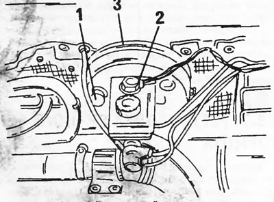
Figure 182. Master brake cylinder and brake booster.

Figure 182. Master brake cylinder and brake booster. 1. Brake fluid level alarm wires; 2. Connecting the vacuum hose; 3. Hydraulic brake booster

  • Remove the two nuts from the brake master cylinder on the front side of the brake booster.
  • Carefully remove the brake master cylinder. To prevent brake fluid from spilling onto painted surfaces, hold a rag under the cylinder or remove the cylinder at an angle as shown in Figure 183.
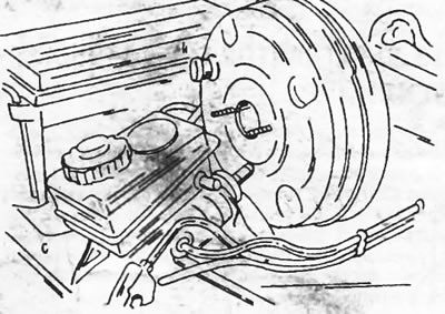
Figure 183. Removing the master brake cylinder from the studs on the power steering in an inclined…

Figure 183. Removing the master brake cylinder from the studs on the power steering in an inclined position


  • Installation of the master brake cylinder is carried out in reverse order. Tighten the fastener to a tightening torque of 20 Nm.
  • Fill the reservoir with fresh brake fluid and bleed the brake system as described in section 13.6. Then bring the brake fluid level in the reservoir to the normal level.

13.4.2. Repair of the master brake cylinder


It is better not to repair the master brake cylinder. If damaged, it is better to install a new cylinder. When purchasing a master cylinder, please specify the vehicle model, as the cylinders are not the same on all models. However, if you have a repair kit, repairing the master brake cylinder is not difficult. In this case, maintaining cleanliness is especially important. The removed cylinder is shown in Figure 184 and can be disassembled as follows:
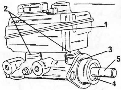
Figure 184. Master brake cylinder. 1. Brake fluid pool; 2. Rubber tips; 3. Rubber gasket; 4.…

Figure 184. Master brake cylinder. 1. Brake fluid pool; 2. Rubber tips; 3. Rubber gasket; 4. Retaining ring; 5. Push rod

  • Remove the dual-chamber brake fluid reservoir (1). It is secured to fittings in rubber caps (2) and should be pulled upward and wiggled when removed. Pull back both rubber tips (2) with a screwdriver.
  • Remove the rubber gasket (3).
  • Remove the retaining spacer ring (4) from the cylinder bore. At the same time, lightly press on the push rod to reduce the pressure on the ring.
  • Slowly release the push rod and pull the piston with the return spring out of the cylinder. These details are shown in Figure 185.
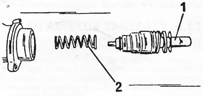
Figure 185. Remove the piston (1) with the return spring (2) from the cylinder.

Figure 185. Remove the piston (1) with the return spring (2) from the cylinder.


  • Unscrew the stop screw from the side of the cylinder. It holds the intermediate piston inside the cylinder. To avoid damaging the piston when unscrewing the screw, press the piston inward with a wooden stick to reduce the pressure on the piston. Remove the piston and the second return spring from the cylinder. To do this, hit the cylinder on a wooden stand or blow out the parts with compressed air.
  • Remove the washer (1), piston seal (2), spacer washer (3), seal (4) and guide pin (5) of the gasket from the piston in sequence.
  • Remove the washer and sealing cuff from the intermediate piston.
  • If further disassembly of the pistons is required, the overpressure valve, O-ring and brass washer can be removed from it.
  • Clean and inspect all parts thoroughly. The cylinder bore should be especially checked. A cylinder with a scratched or corroded working surface must be replaced. Check the patency of all cylinder openings.
  • Before assembly, lubricate all parts with brake fluid.
  • If the overpressure valve was removed, apply a brass washer, install a sealing ring and secure the valve.
  • Place the sealing ring and washer on the intermediate piston.

Assemble the working piston using Figure 186. Sequentially install the guide pin (5), the cuff (4), the spacer washer (3), slide on the seal (2) and press everything together with the washer (1). The piston cuffs have sealing lips, which should be positioned as follows:

* the cuff in front of the piston must face the back of the cylinder,
* The cuff behind the piston must face the front side of the cylinder.
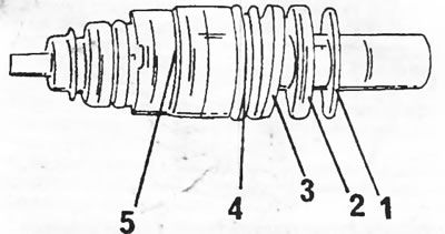


Figure 186. Assembled working piston. 1. Washer; 2. Sealing ring; 3. Expansion washer; 4. Rubber…

Figure 186. Assembled working piston. 1. Washer; 2. Sealing ring; 3. Expansion washer; 4. Rubber cuff; 5. Guide pin

  • Carefully insert the intermediate piston and spring into the hole. The piston has a groove into which the thrust screw fits. To align the screw neck and the groove on the piston, push the piston inward with a wooden stick while tightening the screw. When you feel that the piston no longer wants to return under its own pressure, tighten the screw completely.
  • Carefully insert the spring and working piston and use the pusher to push the piston inward. Insert the retaining ring into the cylinder groove. Check that the ring is securely seated.
  • Finally, install the rubber tips, tank and retaining ring.
This article is available at russian, bulgarian, belarusian, ukrainian, serbian, croatian, romanian, polish, slovak, hungarian
Article reviewed by editor: Bespalov Alexey
Share information:
Previous
Peugeot J5: Brake system
Next

Rear wheel brakes
Front disc brakes
Adjusting the foot brake (service brake)
Brake system — general information
Hydraulic brake booster
Bleeding the brake system
Adjusting the handbrake
Brake force regulator
Cooling system
See similar information for other Peugeot models

➨ Master cylinder — removal, overhaul and refitting Peugeot 106 (1991-2003)
➨ Replacing the master brake cylinder Peugeot 207 (2006-2014)
➨ Replacing the brake master cylinder Peugeot 307 (2001-2008)
➨ Master Brake Cylinder — Removal, Repair and Installation Peugeot 405 (1987-1997)
➨ Brake fluid Peugeot 605 (1989-2000)
Link to this article in different formats
Comments and feedback from visitors
No comments yet


Add two numbers 12 + 13


Partner I (1996-2008) 
  • General information
  • Introduction to the guide
  • Faults en route
  • Weekly checks
  • User manual
  • Maintenance (petrol)
  • Maintenance (diesel)
  • Power unit
  • Petrol engines
  • Diesel engines «XUD»
  • Diesel engines «DW»
  • Overhaul of petrol engines
  • Overhaul of diesel engines
  • Cooling and heating
  • Power and exhaust (petrol)
  • Power and exhaust (XUD diesels)
  • Power and exhaust (DW diesels)
  • Emission reduction
  • Starting and charging system
  • Transmission
  • Clutch
  • Mechanical gearbox
  • Drive shafts
  • Chassis, running gear
  • Brake system
  • Car suspension
  • Steering
  • Body and interior
  • Exterior (external elements)
  • Interior (internal elements)
  • Doors, locks and windows
  • Electrical equipment
  • Equipment and devices
  • Electrical circuits
Peugeot 807 (2002-2014) 
  • General information
  • Operating instructions
  • Maintenance
  • Troubleshooting
  • Power unit
  • Gasoline engines
  • Diesel engines
  • Cooling and heating
  • Fuel injection (petrol)
  • Fuel system (diesel)
  • Fuel system
  • Exhaust system
  • Ignition system
  • Transmission
  • Clutch
  • Manual gearbox
  • Automatic gearbox
  • Chassis, running gear
  • Brake system
  • Car suspension
  • Steering system
  • Body and interior
  • Exterior (external elements)
  • Interior (internal elements)
  • Electrical equipment
  • Power devices
  • Electrical circuits
Peugeot 806 (1994-2002) 
  • General information
  • User manual
  • Maintenance
  • Power unit
  • Petrol engines
  • Diesel engines
  • Lubrication system
  • Cooling system
  • Fuel injection (petrol)
  • Fuel system (diesel)
  • Ignition and exhaust systems
  • ECM Bosch Motronic MP 3.2
  • ECM Magneti-Marelli (MM)
  • Transmission
  • Clutch
  • Mechanical gearbox
  • Chassis, running gear
  • Brake system
  • Car suspension
  • Steering
  • Electrical equipment
  • Equipment and devices
  • Electrical circuits
Peugeot J5 (1981-1993) 
  • General information
  • Introduction to manual
  • Specifications
  • Gasoline engine
  • Engine repair
  • Lubrication system
  • Cooling system
  • Fuel system
  • Ignition system
  • Diesel engine
  • Engine repair (DB9)
  • Lubrication system (DB9)
  • Cooling system (DB9)
  • Fuel injection (DB9)
  • Engine repair (U25)
  • Lubrication system (U25)
  • Cooling system (U25)
  • Fuel injection (U25)
  • Transmission
  • Clutch
  • Gearbox
  • Drive shafts
  • Chassis, running gear
  • Steering system
  • Car suspension
  • Brake system
  • Electrical equipment
  • Power devices
  • Electrical circuits
PeugeotBook.ru © 2018–2026 | Mobile version | Sitemap: EN BG BY UA RS HR RO PL SK HU | Write message | Site search | Add to bookmarks | Peugeot owners
106 (1991-2003) | 206 (1998-2012) | 207 (2006-2014) | 305 (1977-1989) | 306 (1993-2002) | 307 (2001-2008) | 405 (1987-1997) | 406 (1995-2004) | 605 (1989-2000) | Partner-I (1996-2008) | Eurovans-807 (2002-2014) | Eurovans-806 (1994-2002) | J5 (1981-1993) |
Cookies are used to ensure the correct display of pages on the site.