



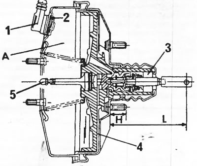
Figure 187 Sectional view of a single-chamber hydraulic booster (A). The cylinders, 203 mm x 229 mm in diameter, have the same shape. 1. Check valve; 2. Sealing tip; 3. Filter; 4. Membrane; 5. Push rod A = working chamber H = height of pin L = length of push rod
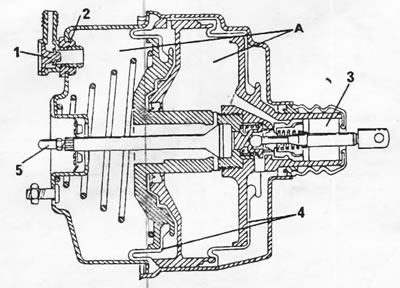
Figure 188. Sectional view of a hydraulic booster with two working chambers. The pressure rod (5) on this hydraulic booster must not be adjusted. 1. Check valve; 2. Sealing tip; 3. Filter; 4. Double membrane; 5. Push rod; A = working chamber;
Adjustment is required only when replacing a single-chamber power steering unit. On models produced before September 1990, the "L" dimension should be set to 105-106 mm. On later models, this dimension should be 113-115 mm. However, the month of the changes is not the same for all models.
(Source available here: www.PeugeotBook.ru)
Sometimes the power steering you need can be found in a car graveyard. The required device is determined by the following features:
- If the stud height (H) is 22.5 mm and the instrument diameter is 203 mm, then this power steering is suitable for models produced before September 1990 (single-chamber hydraulic booster, shown in Figure 187).
- If the stud height (H) is 32.0 mm and the instrument diameter is 203 mm, then this power steering is suitable for models produced from October 1990 onwards (single-chamber hydraulic booster, shown in Figure 187).
- If the stud height (H) is 35.0 mm and the instrument diameter is 229 mm, then this power steering is suitable for models produced from January 1992 onwards (single-chamber hydraulic booster, shown in Figure 187).
- If the power steering looks like the one shown in Figure 188 (two working chambers), then on models produced before June 1990, the height of its studs (H) was 20.5 mm, and was later changed to 29.5 mm.
From the data provided, it is clear that the power steering must be selected specifically for each model.
It should be remembered that when driving downhill with the engine off, after several presses of the brake pedal, all the vacuum is used up and after this the braking system operates without a power steering. Accordingly, the effort required for braking increases, which can affect traffic safety.
To gain access to the power steering, the brake master cylinder must be removed. It can be removed after unscrewing the nuts from the four studs in the car's interior. To access the nuts, you need to remove the spare wheel mount. The brake master cylinder can be folded back as shown in figure 183. This is enough to pull out the power steering.
A bolt is used to secure the push rod to the brake pedal. The power steering is secured with three nuts in the pedal area on the bulkhead. Disconnect the vacuum hose from the fitting (1) on figure 182.
The filters at the end of the power steering push rod can be replaced. To do this, remove the dust cover, remove the filter mount and press out the filter with a sharp object. To install new filters on the traction, they must be cut from the inside out.
When replacing a single-chamber power steering (Figure 187) the push rod length needs to be adjusted. It is produced after loosening the lock nut by turning the fork head. The corresponding dimensions are shown below Figure 187.
On these power steering systems, the length of the push rod (5) must also be adjusted. For control, use a ruler to measure the size of the push rod (5) in Figure 187. The rod must protrude by 0.3—0.5 mm. Otherwise, loosen the lock nut and adjust the traction.
The installation of the brake booster is carried out in reverse order.