



Table of contents: 13.2.1. Replacing brake pads 🠇 13.2.2. Brake caliper repair 🠇 13.2.3. Brake discs 🠇
13.2.1. Replacing brake pads
To check the thickness of the brake pad lining material, remove the wheels and check the thickness of the remaining material through the inspection window in the caliper. Always check from both sides, as uneven wear of the brake pads may occur. If this happens, you may suspect that the caliper is jammed, which requires removal and inspection.
Brake pads must be replaced if the thickness of the material does not exceed the thickness of two folded matches. The official minimum acceptable thickness of brake pad material is 2.0 mm.
When removing brake pads and intending to reinstall them, the pads should be marked to ensure they are installed in their original locations. In this case, the wheel from which the pad is removed and its position in the caliper are marked. If the brake pads are installed in the wrong places, the car may slow down.
The brake caliper consists of two halves. Do not separate the caliper halves under any circumstances.
Removing the brake pads is done as follows:
- Loosen the wheel bolts on both sides.
- Place the front of the vehicle on stands and remove the front wheels. The steering knuckles should sag under their own weight.
- Disconnect the wear indicator sensor wire connector.
- Insert the water pump removal pliers between the brake caliper and the inner brake shoe (1) in Fig. 168. When the pliers are squeezed, the piston is pressed into the cylinder.
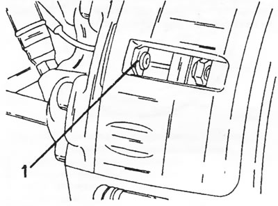
Figure 168. To press the piston into the cylinder, insert the water pump removal pliers between the brake caliper and the inner brake pad (1).
- Before removing the brake caliper, refer to Figures 169 and 170. Loosen the bolt (1) in Figure 169, using a second open-end wrench to prevent the guide pin (2) in Figure 170 from turning.
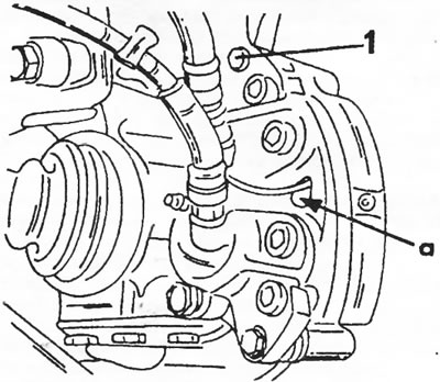
Figure 169. Bolt (1) holds the top side of the brake caliper to the guide pin (sliding finger) When removing, pull the brake pad wear sensor wire through hole "a".
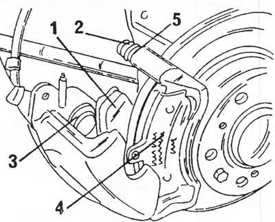
Figure 170. Brake caliper with the caliper cylinder folded back. 1. Inner brake shoe; 2. Guide pin; 3. Cylinder boot; 4. Outer brake shoe; 5. Guide pin sealing ring
- Tilt the brake caliper downwards to the position shown in Figure 170. After this, the brake shoe (1) on the inner side and the brake shoe (4) on the outer side can be pulled out.
Clean the inside of the brake caliper bore with a stiff brush, removing dust from the brake pads. The pistons should now be recessed into the holes all the way if they stick out too far. For this you can use a wooden block (for example, with a hammer handle), but be careful - due to the pressure on the pistons, the brake fluid in the line is displaced and the level of the brake fluid in the reservoir rises so much that the fluid may leak out of the reservoir. To avoid this, you can pump out some of the liquid from the tank or open the air release valve by pressing the piston. If the valve is opened just a little and only for the duration of the piston movement, there is no need to bleed air from the brake system.
- If it is necessary to replace the seal (5) in Figure 170, unscrew the guide pins (2). Thoroughly clean the guide pins and install them with a new seal. Lubricate the guide pins with brake grease. The type of lubricant is known at the service station.
Installation of brake pads is carried out in the reverse order according to the following description:
- Install the inner brake shoe (1) and outer brake shoe (2) in Fig. 170 in the correct position. There is a brake pad wear sensor wire on the inner brake pad. The wire must be passed through hole "a" shown in Figure 169.
- Check the brake pad installation again and tilt the brake caliper upwards to a position where the bolt can be screwed in from the top side. New bolts are included with the brake caliper repair kit and must be replaced. If new bolts are not available, lubricate the bolt threads with Loctite.
- While holding the guide pin 92) in Figure 170 with a wrench to prevent it from turning, tighten the bolt (1) in Figure 169 to a torque of 34 Nm.
- Connect the brake pad wear sensor wire. Check that the brake pad wear sensor wire does not contact the brake components of the front wheel suspension.
- Press the brake pedal several times. This is important for installing new brake pads. At the same time, the force applied to the brake pedal is checked. From here you can determine whether the brake system needs to be bled if air has entered the system through an open valve (when the valve opened when the piston was recessed).
- Put the wheels on and lower the car. Tighten the wheel bolts immediately.
- Check and, if necessary, adjust the brake fluid level in the reservoir.
- Remember that new brake pads need to be broken in before they provide full braking performance. Therefore, brake carefully at first.
13.2.2. Brake caliper repair
Unscrew the brake caliper from the steering knuckle. The support is secured with two bolts from the inside. Since two brake hoses are installed, it is necessary to disconnect the hoses from the brake pipe fitting. Otherwise, the hose could be unscrewed after loosening the hex key and unscrewing the brake caliper. To loosen the connection, unscrew the union nuts. Knock both leaf springs out of their mountings and pull out the brake hoses.
All repair work should be carried out on a clean workbench with strict observance of cleanliness. The brake pads can now be removed as described above (this could have been done before removing the mounting frame). Before you begin, please read the following instructions. They concern all hydraulic elements.
- When disassembling the part, replace all rubber seals or oil seals. During operation, parts wear out and, although they may still have a good appearance, for safety reasons they must be replaced.
- Never install a piston that has scratches or is corroded. In this case, it is necessary to install a new part. Use only alcohol or clean brake fluid to clean parts. For example, even a small amount of gasoline will immediately or later attack rubber parts, causing them to swell and potentially affect the functioning of the braking system during subsequent use. The alcohol used for cleaning leaves stains that can be wiped off with a lint-free cloth.
Figure 171 shows the brake caliper with the brake pads removed. The figure shows four bolts (2) holding the two halves of the brake caliper together. Do not loosen or remove these bolts under any circumstances.
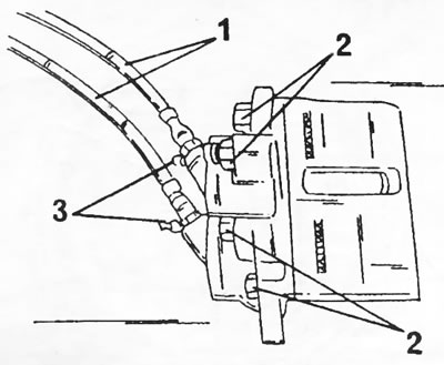
Figure 171. Brake caliper cylinder with brake pads removed. 1. Brake hoses; 2. Brake caliper halves bolts (don't turn away); 3. Air release valve screws
- Unscrew both brake hoses (2) from the hexagon and remove the air bleed screws (3).
- Push the pistons out of the holes using compressed air. To prevent the pistons from hitting the metal on the other side when blowing, insert a piece of hard wood into the hole in the brake caliper. When connecting to the compressed air line, remove your fingers from the blow-out area. The work procedure is shown in Figure 172. If necessary, the work can be carried out at a gas station where it is possible to connect to the compressed air line.
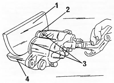
Figure 172. Blowing out pistons from the brake caliper with compressed air. 1. A piece of wood; 2. Piston; 3. Anthers; 4. Brake caliper cylinder
- Remove the cylinder seals from the inside of the cylinder bores using a sharp object. Do not damage the holes.
- Clean all parts with clean brake fluid or alcohol. Replace parts if necessary. Rubber parts must be replaced. It is imperative to use the repair kit.
- Lubricate the O-rings with clean brake fluid or brake lubricant and insert the rings into the cylinder grooves.
- Place dust boots on the pistons and insert the piston together with the ring into the cylinder.
- Place the dust boot ring into the groove of the cylinder body. After assembly, check the fastening of the dust boot ring in the piston and in the housing.
- Screw the brake hoses to the brake caliper.
- Thoroughly clean the surfaces of the brake caliper and steering knuckle.
- Lubricate the brake caliper bolt threads with Loctite, place the brake caliper on the steering knuckle and tighten the bolts.
- Tighten both bolts in several passes to a torque of 145 Nm.
- Install brake pads (section 13.2.1.).
- Slide the brake hoses into the mounting brackets and secure with leaf springs. Secure both brake pipes with union nuts. Check that the brake hoses are not twisted after tightening. If the hoses are twisted, loosen the connection to the brake pipes, turn the hose to the correct position and tighten the union nut again.
- Bleed the brake system (section 13.6.).
13.2.3. Brake discs
If there are scratches or other damage, the brake discs must be replaced (damage occurs, for example, when brake pads wear down to the metal). Measure the thickness of the brake disc using a micrometer or calipers and compare it with the data given in the tables of sizes and adjustments. If the discs are still approximately the same thickness as the original ones, they can be turned.
Replacing brake discs is carried out as follows:
- Loosen the wheel nuts, place the front of the vehicle on stands and remove the wheel.
- Remove the brake pads as described in section 13.2.1.
- Remove two bolts from the wheel hub. One bolt secures the brake disc, the second serves as a wheel guide pin. The brake disc has a tight fit on the wheel hub and therefore needs to be pressed out. Screw three M10 x 1.25 bolts into the three threaded holes. By tightening the bolts evenly, the brake disc will be pressed out of the wheel hub. Do not allow the brake disc to fall.
- Place a new brake disc on the hub and hammer it in with a rubber hammer.
- Insert the bolts and tighten them alternately in a cross pattern.
- Place a dial indicator on the ground next to the brake disc on a suitable stand or place the indicator on the steering knuckle and measure the runout of the brake disc. Place the indicator's feeler gauge against the outer edge of a well-cleaned brake disc (about 5 mm from the edge) and slowly turn the brake disc. The deviation of the indicator needle represents the brake disc runout, which should not exceed 0.15 mm. If the runout is unacceptably high, a foreign object may be lodged between the wheel hub and the brake disc. The dial indicator on a long stand can also be mounted, as shown in Figure 173, on a supported wheel. Check the runout before installing the brake pads, as in this condition the wheel hub and brake disc turn more easily. This makes measurement easier.
- Install the wheel, lower the vehicle and tighten the wheel nuts to the specified torque.
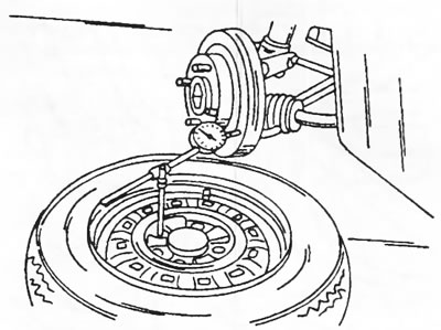
Figure 173. Brake disc runout can also be measured using the method described.