



13.2.1 Replacing brake pads
To check the thickness of the working material of the brake pads, remove the wheels and check the remaining thickness of the working material of the brake pads. If the thickness is less than two folded matches, the brake pads must be replaced.
If the brake pads are still suitable for use, then when removing them, they should be marked so that they can be installed in their original places. Failure to observe the correct installation location of the brake pads may subsequently cause wheel drag.
Installation of brake pads, depending on the design of the brake calipers, is carried out as follows:
Bendix brake caliper
- Place the front of the vehicle on stands and remove the front wheels.
- Using Figure 257, remove both spring bars (1) from the sliding wedges (2) between the brake caliper and the brake housing. Disconnect the electrical brake pad wear indicator wire.
- Press the brake caliper upwards and pull out the lower wedge.
- Use a screwdriver to push out the top wedge.
- Press the brake caliper side down by inserting a pry bar between the caliper and the shock absorber strut and pull out the outer brake pad.
- Press the brake caliper to the other side and pull out the inner brake pad.
- A deep groove is machined into the working material of the brake pad, the bottom of which does not reach the metal plate of the pad by 1.5 mm. This groove allows you to quickly determine the wear of the brake pad. If the groove is almost invisible, the pad thickness is approaching its maximum value. The actual purpose of the groove is to drain water and dirt away from the brake disc, which penetrates between the brake disc and the brake pad.
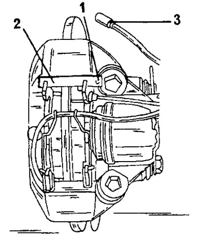
Figure 257. Removing and installing brake pads on a Bendix brake caliper. 1. Spring bar; 2. Sliding wedges; 3. Wire
Before installing new brake pads, check the degree of wear of the brake disc and remove corrosion from the inside and outside. Remove the expansion tank cap and pump out some brake fluid from it (avoid contact of brake fluid with painted surfaces).
Installation of brake pads is carried out as follows:
- Press the piston into the hole with a wooden stick. At the same time, do not allow the brake fluid to leak out of the expansion tank. The key shown in Figure 258 can also be used to carefully push the piston in.
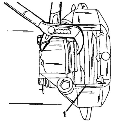
Figure 258. Press the piston into the hole with a pipe wrench without damaging the piston. First insert the lower wedge (1).
- Lightly lubricate the lower wedge with graphite grease.
- The brake pads have offset linings, meaning they can be installed either only on the left or only on the right. Therefore, before installing a new pad, compare it with the removed brake pad.
- Insert the inner brake shoe.
- Insert the outer brake shoe from the other side.
- Press both brake pads against the lower edge of the brake caliper and push in the upper sliding wedge, then drive it in completely.
- Check that the brake caliper can move in and out and lock the sliding wedges with spring bars.
- Install the wheels, lower the vehicle and tighten the wheel nuts (tightening torque 85 Nm). Press the brake pedal several times to bring the brake pads into contact with the brake disc.
It is important to remember that new brake pads must be run in before they achieve their full functionality.
ATE Teves brake caliper
- Place the front of the vehicle on stands and remove the front wheels.
- Using Figure 259, disconnect the brake pad wear sensor connector (1).

Figure 259. Removing and installing the ATE Teves brake caliper. 1. Wire connector; 2. Caliper bolts; 3. Tension spring
- Remove the two bolts (2) from the side of the brake caliper.
- Use a screwdriver to remove the tension spring (3) from the brake caliper.
- Grasp the brake caliper from below and tilt it upwards as shown in Figure 260. In this position, secure the brake caliper to the front wheel suspension with a piece of cord or wire so that it cannot fall.
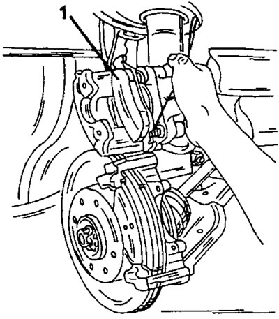
Figure 260. After folding back the brake caliper cylinder, the brake pads (1) can be removed from the left and right of the brake disc. The upper brake shoe must be removed from the piston.
- Remove both brake pads. The inner brake pad is secured to the piston with a clamp.
Clean the inside of the brake caliper bore with a stiff brush to remove brake dust. After this, you should press the piston to the bottom of the brake caliper hole, that is, in the direction of the arrow in Figure 261. This is best done using a special key. Otherwise, use a wooden stick (for example, with a hammer handle) and carefully push the piston down, but be careful - when you press the piston, the brake fluid is forced out of the hydraulic line and its level in the expansion tank of the master brake cylinder rises so much that it can leak out. To avoid this, you can pump out some brake fluid from the expansion tank or, when recessing the piston, slightly open the air release valve only when the piston moves, so that there is no need to remove air from the brake system.
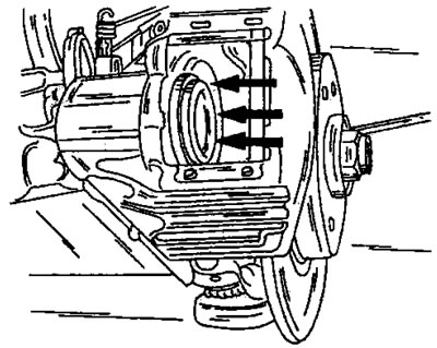
Figure 261. Before installing the brake pads, depress the piston in the direction of the arrows.
Installation of brake pads is carried out as follows:
- Insert the outer brake shoe and connect the inner brake shoe to the piston.
- Release the brake caliper from the cable mount and carefully lower it down, being careful not to damage the brake pads.
- Insert and tighten both bolts (2) in Fig. 259 evenly to a tightening torque of 20 Nm.
- Connect the brake pad wear sensor wire. Check if the wire touches other suspension parts.
- Insert the spring (3). Press on its middle part and insert the ends into the holes in the brake caliper.
- Press the brake pedal several times. This is very important to ensure that the brake pads are in the correct position. Check the pedal pressure at once. Based on the resistance force, one can conclude that it is necessary to remove air from the brake system if air has entered the brake system when the air bleed valve is opened (if when the piston was recessed it opened).
- Check the brake fluid level in the expansion tank of the master cylinder and, if necessary, adjust it.
- It is important to remember that new brake pads must be run in before they achieve their full functionality. Therefore, at first, try to brake carefully.
13.2.2 Brake caliper repair
- Unscrew the brake caliper from the steering knuckle and perform all disassembly work on a clean workbench with utmost care. Before starting work, please read the following instructions. These instructions apply to all parts of the hydraulic system.
- When disassembling the part, replace all rubber seals or gaskets. During operation, parts wear out and although they may still look good, from a vehicle safety point of view they must be replaced.
- Never reinstall a piston or cylinder if its surfaces are found to be scratched or corroded. In this case, it is necessary to install a new part. To clean parts, use only alcohol or clean brake fluid. For example, even a very small amount of gasoline will immediately or later attack rubber parts, causing them to swell and negatively affect the functioning of the brakes. The alcohol used for cleaning leaves stains that can be wiped off with a clean, lint-free cloth. Overhaul and repair are described separately for each type of brake caliper.
Bendix brake caliper
Using Figure 262:
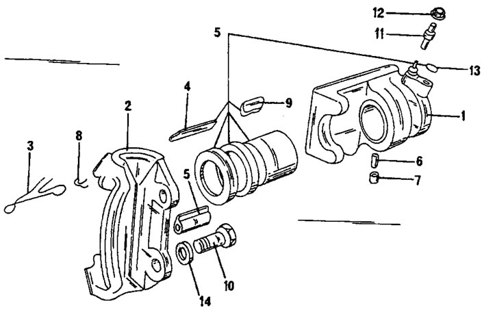
Figure 262. Bendix brake caliper assembly drawing. 1. Support bracket with cylinder; 2. Brake body; 3. Caliper spring; 4. Sliding wedge; 5. Sliding wedge; 6. Locking spring; 7. Constipation; 8. Bolt spring; 9. Spring bar; 10. Bolt; 11. Air release valve; 12. Protective cap; 13. Copper sealing ring; 14. Washer; 15. Repair kit
- Remove the brake pads (section 13.2).
- Disconnect the brake hose from the brake caliper. If you have a clamp, clamp the hose in the middle to prevent brake fluid from leaking out and air from entering the hydraulic system. The hose can also be unscrewed from the brake line. In this case, disconnect the hose from the brake caliper after this.
- Using a small screwdriver, remove the dust cap without damaging the cylinder.
- Connect the compressed air line and blow out the piston. To prevent the piston from hitting the metal on the other side, insert a piece of wood into the hole in the brake caliper. If necessary, this work can be done at a gas station where there is a compressed air line.
- Use a sharp object to pull out the cylinder sealing ring from the inside of the cylinder bore. Be careful not to damage the hole.
- Clean all parts with alcohol or clean brake fluid and inspect thoroughly. Rubber parts must be replaced. For this purpose it is necessary to use a repair kit.
- Lubricate the cylinder O-ring with clean brake fluid or brake lubricant and insert it into the groove in the cylinder bore.
- Place the dust cap on the piston and insert the piston into the hole together with the ring.
- Insert the dust cap into the groove in the cylinder body. After assembly, check the fastening of the dust cap on the piston and in the housing. Figure 263 shows the assembled cylinder.
- Screw the brake hose onto the brake caliper without tightening the hose.
- Thoroughly clean the surfaces of the brake caliper and steering knuckle.
- Lubricate the brake caliper bolt threads with Loctite paste, place the brake caliper on the steering knuckle and screw in the bolts.
- Tighten the two bolts shown in Figure 264 in several passes to a torque of 110 Nm.
- Install brake pads (section 13.2).
- Tighten the brake hose onto the brake caliper and check that it does not twist when tightening. If this happens, loosen the brake pipe connection, turn the brake hose to the correct position and tighten the union nut again.
- Remove air from the brake system (section 13.5).
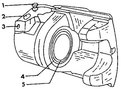
Figure 263. Assembled Bendix brake caliper. 1. Air bleed valve; 2. Hose connection point; 3. Connection hole; 4. Dust cap; 5. Piston
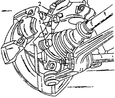
Figure 264. Fastening the brake caliper to the steering knuckle. The arrows (1) indicate the mounting bolts. At location (2) the brake hose mount is shown
ATE Teves brake caliper
Disassembly of the brake caliper is carried out using Figure 265. Unscrew the brake caliper from the steering knuckle to perform the work on a clean work bench.

Figure 265. Assembly drawing of the ATE Teves brake caliper. 1. Upper sliding bushing; 2. Rubber bushing; 3. Brake caliper cylinder; 4. Cylinder seal; 5. Piston; 6. Dust cap; 7. Lower sliding bushing; 8. Rubber cuff; 9. Air bleed valve
- Remove the brake pads following the instructions section 13.2.
- Loosen the brake hose fastening on the brake caliper. This way you can leave the hose attached to the brake pipe. To prevent large amounts of air from entering the hydraulic system, you can clamp the hose.
- Loosen the two brake caliper mounting bolts. The location of the brake caliper mounting bolts is shown in Figure 259.
- Unscrew the brake hose from the brake cylinder.
- Secure the brake caliper in a vice and remove the dust ring from the cylinder (see Figure 266). In this case, you should carefully lift the sealing lips with a screwdriver.
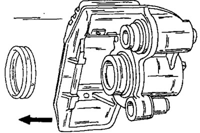
Figure 266. Removing the dust ring from the piston and cylinder body.
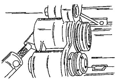
Figure 267. Blowing out the piston from the cylinder. Keep fingers away from dangerous areas.
- Place a piece of wood into the brake caliper hole and connect the compressed air line to the brake caliper nipple. If there is no compressed air, take the brake caliper to a gas station and perform the piston removal work where there is usually a compressed air line. Keep your fingers out of the expected path of the piston as the piston hits the piece of wood at high speed.
- Use a sharp object to pull the seal (4) out of the cylinder hole without damaging the hole walls. Discard the seal immediately as it must be replaced.
- Secure the brake caliper in a vice (through tin or aluminum spacers) and use a small punch to knock out the small sliding bushing (1) in Figure 265. After this, pull out the rubber bushing. Remove the large sliding bushing (7) and rubber seal (8) from the other side in the same manner. This work is only performed if the rubber parts are in poor condition.
- Inspect all parts for wear and damage and replace if necessary. Brake caliper repair kits are available, and all parts should be used, even if some are still in good condition.
Assembly is carried out in reverse order, taking into account the following points:
- Lubricate the cylinder sealing ring with brake fluid and insert it into the cylinder bore groove with your fingers. Press the ring firmly into the groove.
- Lubricate the outside of the piston with brake fluid and pull the dust protection ring onto the piston, with the lug facing the piston groove. First insert the piston into the hole. Lightly press the dust ring against the bore in the cylinder body and insert it into the groove, while simultaneously turning the piston in the direction shown in Figure 268. After the dust ring is seated in the cylinder, insert the lug into the piston. For this purpose, use the tool shown in Figure 269. Such a device can be easily found. After installation, turn the tool with the flat side pressed against the piston in the hole. After the piston groove is positioned opposite the dust ring, insert the lug into the groove.
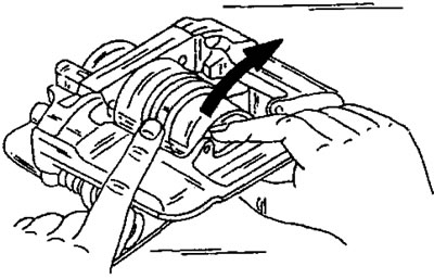
Figure 268. Installing the dust ring in the piston and cylinder bore. In this case, turn the piston in the direction of the arrow.
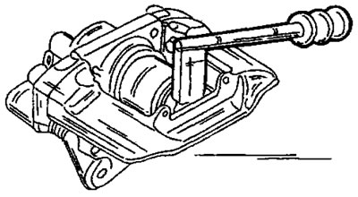
Figure 269. Using a special tool to press the piston into the hole. Such a device is easy to make.
- Insert the larger rubber bushing from the inside of the cylinder body and then push the bushing from the outside into the rubber bushing and into the brake caliper. These are parts (8) and (7) in Figure 265.
- Using Figure 270, insert a new rubber bushing into the brake caliper from the outside and then insert the metal bushing into the rubber bushing and into the cylinder body. Its details (2) and (1) in Figure 265.

Figure 270. Installing the upper sliding bushing. Insert both parts in the indicated position.
- Clean the piston surface and the adjacent surface from brake fluid or brake grease, depending on what was used for lubrication, and screw the brake hose onto the brake caliper, tightening it with your fingers.
- Thoroughly clean the surfaces of the brake caliper and steering knuckle and install the brake caliper. Tighten the two mounting bolts (120 Nm).
- Finally, install the brake pads. Both sliding finger bolts are tightened to a torque of 30 Nm.
13.2.3 Brake discs
If there are scratches or other damage, the brake discs must be replaced (damage occurs, for example, when brake pads wear down to the metal). Measure the thickness of the brake disc using a micrometer or calipers and compare it with the data given in the tables of sizes and adjustments. If the discs are still approximately the same thickness as the original ones, they can be turned.
Replacing brake discs is carried out as follows:
- Loosen the wheel nuts, place the front of the vehicle on stands and remove the wheel.
- Remove the brake pads.
- Remove two bolts from the wheel hub. One bolt secures the brake disc, the second serves as a wheel guide pin. Make sure the bolts don't fall through.
- Place a new brake disc on the hub and hammer it in with a rubber hammer.
- Insert the bolts and tighten them alternately in a cross pattern.
- Place a dial indicator on the ground next to the brake disc on the appropriate stand (figure 271 shows how the wheel can be used for this purpose) or place an indicator on the steering knuckle and measure the runout of the brake disc. Place the indicator's feeler gauge against the outer edge of a well-cleaned brake disc (about 5 mm from the edge) and slowly turn the brake disc. The deviation of the indicator needle represents the brake disc runout, which should not exceed 0.10 mm. If the runout is unacceptably high, a foreign object may be lodged between the wheel hub and the brake disc. In this case, unscrew the disc and check the surfaces. The runout of the brake disc should be measured before installing the brake pads, so that it is easier to turn the wheel hub and, consequently, the brake disc.
- Install the wheel, lower the vehicle and tighten the wheel nuts to the specified torque (85 Nm).
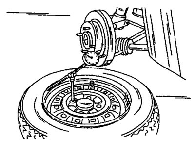
Figure 271. Measuring brake disc runout.