



Table of contents: 13.3.1. Removing brake pads 🠇 13.3.2. Installing brake pads 🠇 13.3.3. Wheel brake cylinder 🠇
All vehicles are equipped with either Bendix or Girting brakes. Both braking systems are shown in Figures 272 and 273.
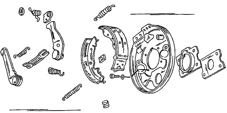
Figure 272. Bendix rear wheel brake assembly drawing.
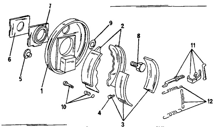
Figure 273. Assembly drawing of the Girling rear wheel brake. 1. Brake shield; 2. Brake pads; 3. Brake shoe linings; 4. Rivet; 5. Plug; 6. Sealing board; 7. Oil separator; 8. Bolt; 9. Washer; 10. Fasteners; 11. Clearance adjustment details; 12. Springs
13.3.1. Removing brake pads
- Loosen the wheel nuts.
- Place the rear of the car on stands and remove the rear wheels.
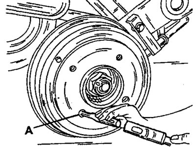
Figure 274. Removing the brake drum. Insert a screwdriver or rod into hole "A" and hit.
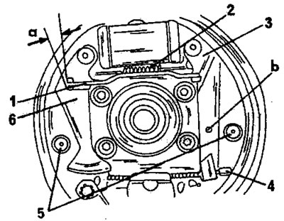
Figure 275. Installed Bendix brake pads, "a" is the gap mentioned in the text. 1. Handbrake pressure plate; 2. Upper return spring; 3. Handbrake lever; 4. Handbrake cable; 5. Brake shield pins and springs; 6. Automatic brake shoe setting lever
- Remove the brake drum and wheel hub. If the brake drum does not come off immediately, tap it in a circle with a plastic or rubber hammer. If the brake drum still cannot be removed, insert a screwdriver from the front side of the brake drum (Figure 274) and hit the handbrake lever to unlock the brake shoe installation mechanism. At the same time, the screwdriver presses on the handbrake lever and lifts the protrusion of the lining from its lock. This allows the brake pads to be set to their center position.
- Further removal work differs for both brake designs.
Bendix brakes
- Using Figure 275, disconnect the upper return spring.
- Grasp the handbrake cable with pliers and pull it outward until the springs are compressed so that the cable can be disconnected from the handbrake lever.
- Before carrying out subsequent removal work, measure the gap "a" of the handbrake pressure plate. If this gap goes beyond 1.0 - 1.2 mm, then there is wear on some parts that must be replaced before assembly.
- Remove the pins (5) of both brake pads. To do this, press the head of the pin with your finger from the back of the brake shield, and from the front of the brake shoe, grab the spring cup with pliers. Rotate the spring cup so that the pin head can be released from the spring cup retainer. Remove the cup and spring and pull out the pin from the back.
- Perform the same work with the other brake pad. Figure 276 shows another view of an open brake with the arrangement of the named parts.
- Press the lever (6) in Figure 275 against the axle butt and release the pressure bar (2) of the handbrake.
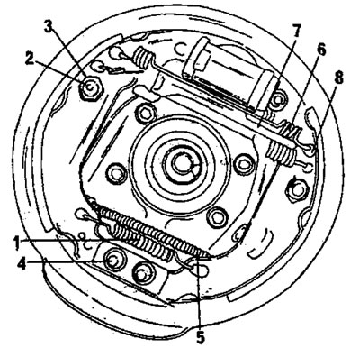
Figure 276. Bendix brake. 1. Lower return spring; 2. Mounting pin on the brake shield; 3. Cup of spring; 4. Bottom stop; 5. Handbrake cable; 6. Upper return spring; 7. Pressure plate; 8. Brake pads
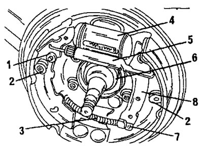
Figure 277. Girling brake. 1. Expansion washer; 2. Support pin and springs; 3. Lower return spring; 4. Wheel brake cylinder; 5. Pressure plate; 6. Seal; 7. Handbrake cable; 8. Handbrake lever
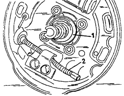
Figure 278. View of the brake shield after removing the brake pads. 1. Seal; 2. Handbrake cable
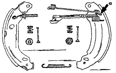
Figure 279. Disassembled Bendix brake components. Connect the spring hook as shown.
- Return the lever (6) to its original position and remove both brake pads. Disconnect the lower return spring.
Girling brakes
- Using Figure 277, disconnect the handbrake cable (7) from the lever (8). Grasp the handbrake cable with pliers and pull it outward until the springs are compressed so that the cable can be disconnected from the handbrake lever.
- Using a screwdriver or pliers, disconnect the upper return spring and the automatic brake shoe setting mechanism spring.
- Remove the ratchet and spring. There is a spacer washer (1) under the ratchet axle which must not be lost.
- The brake shield support pins are removed in the same way as on Bendix brakes.
- Move the brake pads apart and remove the pressure plate (5) from the upper side and the lower return spring (3) from the lower side. The pressure bars are repositioned and the sides of their installation should be marked. You should also mark which side the adjustment wheel is located on. The end located further from the setting wheel enters the handbrake lever.
- Remove the oil seal from the axle butt. Figure 278 shows the view of the brake shield after removing the brake pads. Only the oil seal and the handbrake cable remain on the brake shield.
- Thoroughly clean all parts, including the brake shield. If the parts are washed with gasoline, it should not come into contact with the rubber caps of the wheel brake cylinder. If the thickness of the brake pad linings is less than 2.0 mm, the pads are replaced. Brake pads can be replaced separately, but this is not recommended. If the wheel brake cylinder shows signs of leakage, it should be replaced as it cannot be repaired.
13.3.2. Installing brake pads
Bendix brakes
Figure 279 shows the Bendix brake components. When installing the brake pads, follow these instructions:
- When installing new brake pads, move the handbrake lever to them. To do this, remove the spring bar from the inside of the brake shoe and remove the lever. The spring bar must be replaced.
- Using Figure 280, engage the pressure plate with the brake shoes. Secure the brake shoe installation mechanism with two springs. Ensure the correct position of the installation mechanism lever. Check the position of the pads from the front and rear.
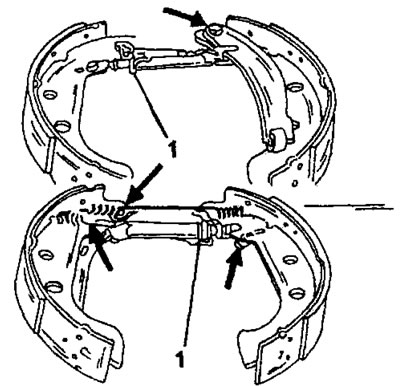
Figure 280. Bendix brake assembly. To ensure proper spring connection, pay particular attention to the areas indicated by the arrows. Place the adjustment wheel as shown in the figure.
- Connect the lower return spring from the inside. The spring hooks must be adjacent to the outside.
- Grasp the end of the handbrake cable and with your other hand hold the return spring and compress the spring. Once the brake cable is released, connect it to the handbrake lever. Check the fastening of the handbrake cable on the lever.
- Take the brake pads as shown in Figure 281 and place them on the brake shield. Move the pads apart from below and place them against the lower stop. Use pliers to stretch the return spring and connect it to the other side.
- insert the support pins (1) in Fig. 282 from the rear side of the brake shield and put on the spring and spring cup from the front side. While holding the pin from the back with your finger, press the pin from the front using pliers. Once the pin is in the hole, turn the spring cup until it is secured by the pin.
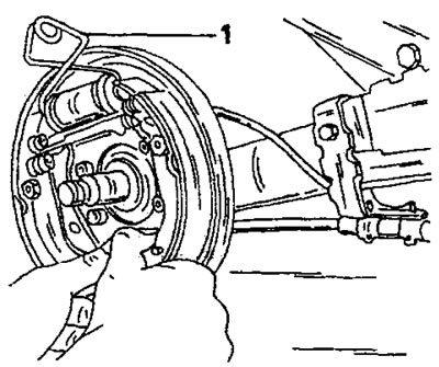
Figure 281. Insert the brake pads from above into the wheel brake cylinder and spread them from below so that they can rest against the lower stop. The spring clip (1) prevents the pistons from coming out.
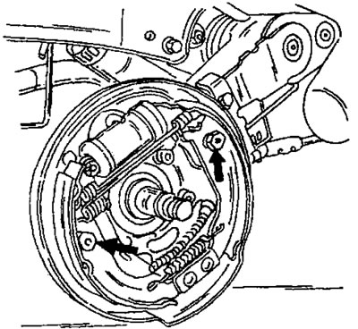
Figure 282. Secure both support pins in the manner described.
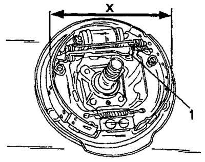
Figure 283. To set the brake pad diameter, turn the setting wheel.
- Center the brake pads on the brake shield and measure the diameter of the pads with a caliper. By rearranging the small wheel (1) in figure 283, set the diameter of the pads to 177 mm.
- Place a new oil seal on the axle butt. The sealing lips must face outward.
- Install the brake drum onto the axle butt following the instructions in section 12.1.4.
- Press the brake pedal at least 30 times until the brake pad setting mechanism returns to its original position and the brake pads are centered. The engine must be running. Finally, the handbrake should be adjusted.
Girling brakes
- When replacing brake pads, it is necessary to move the handbrake lever to the new pads. The assembly of parts is carried out in accordance with Figure 284.
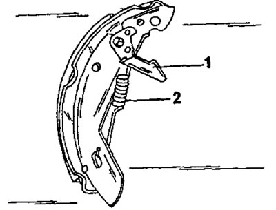
Figure 284. Correct position of the adjusting lever (1) and return spring (2) on the Girling brake.
- Lubricate the threads of both adjusting elements and screw them into the clamping rod. The pressure rods are not the same. The rod that has a right-hand thread is installed on the right side, and the clamping rod with a left-hand thread is installed on the left side. Adjust the clamping rods so that the fork rests against the adjusting wheel.
- Connect the lower return spring. The spring hooks must be positioned correctly.
- Connect the handbrake cable from the inside. To do this, compress the spring, connect the end of the cable to the lever and release the spring again. Check the cable fastening.
- Place the brake pads on the brake shield, spread their upper sides and insert the pressure plate with the correct side facing up. When inserting the brake pads into the wheel brake cylinder, be careful not to damage the rubber seals.
- Install the support pins in the same manner as on Bendix brakes. See also Figure 282.
- Connect the upper return spring to one of the brake shoes, stretch the spring and connect it to the other brake shoe.
- Center the brake pads on the brake shield and measure the diameter of the pads with a caliper. By adjusting the adjuster with a screwdriver, set the diameter of the pads to 177 mm.
- Following the instructions in section 12.1.4, install the brake drum and wheel hub.
- Press the brake pedal at least 30 times until the brake pad setting mechanism returns to its original position and the brake pads are centered. The engine must be running. Finally, the handbrake should be adjusted.
- Put the wheels on and lower the car.
13.3.3. Wheel brake cylinder
The wheel brake cylinder has a pressure compensation device and cannot be disassembled and repaired. During production, the diameter of the wheel brake cylinder changed, so when purchasing a new brake cylinder, you should indicate the chassis number of the car.