



Table of contents: 13.6.1 Replacing brake pads 🠇 13.6.2 Removing and installing the…🠇 13.6.3 Repair of the brake caliper 🠇 13.6.4 Brake discs 🠇
13.6.1 Replacing brake pads
Brake pads should be replaced when they are worn to a thickness of approximately 6.0 mm, including the metal plate. The rear wheels are equipped with Bendix disc brakes only. To remove the brake pads, proceed as follows:
- Place the rear of the car on stands and remove the wheels.
- Pull out the spring bar (1) in Figure 285 and use a small punch to knock out one of the guide wedges (2).
- Remove the brake pads. After this, do not press the brake pedal.
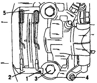
Figure 285. Removing and installing the rear wheel brake pads. 1. Mounting plate; 2. Guide wedge; 3. Brake caliper bolt, 120 Nm; 4. End of the handbrake cable; 5. Brake caliper
- Check the condition of the dust rings and also make sure that the protective rubber seals of the sliding fingers are in good condition. If they need to be replaced, clean the end of the piston and both pins with clean brake fluid and lubricate with brake grease. Install new rubber parts.
Installation is carried out as follows:
Press the piston into the hole. The piston should be simultaneously rotated and pushed into the cylinder, as indicated by the arrows in Figure 286. Two strong screwdrivers are best for this job, with the screwdriver used to rotate the piston having a 7 mm square end. The tip of the screwdriver used to push the piston in should not be applied to the working surface of the brake disc, to avoid scratching it. Figure 287 shows how to use both screwdrivers and in which direction they should be turned.
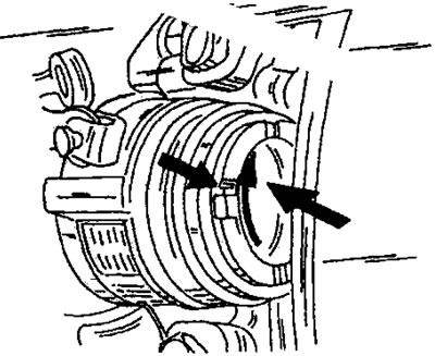
Figure 286. Rotational movement of the brake piston when it is depressed (arrows).
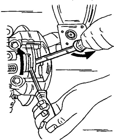
Figure 287. Using two screwdrivers to countersink the brake caliper piston. Use one screwdriver to press on the piston and use the other screwdriver to turn it.
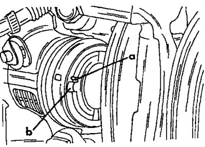
Figure 288. Installation position of the brake piston a - Label; b - 7 mm wide notch
[You can find the original on the page: PEUGEOTBOOK]
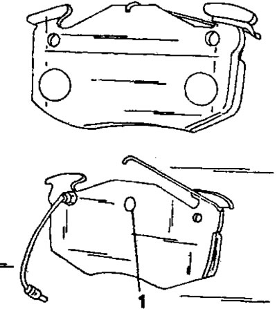
Figure 289. Brake shoe with retaining springs and guide pin (1) (bottom) with wear sensor lead.
- After the piston has been recessed as far as possible, position it as shown in Figure 288, i.e. mark (a) should be located under recess (b) in the piston.
- Replace the springs with new brake pads (Figure 289).
- Insert the brake pads. To do this, engage the journal (1) in Figure 289 into the recess (b) of the brake piston in Figure 288.
- Align the brake pads in the brake caliper bore and insert and drive in the guide wedge (2). Press the brake pads upward to allow the wedge to pass through. Secure the wedge with a spring bar (1).
- After installation, press the brake pedal several times with the engine running to apply pressure to the brake pads.
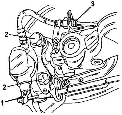
Figure 290. Removing the rear wheel brake caliper. 1. Handbrake cable lever; 2. Bolts, 120 Nm; 3. Connecting the brake hose
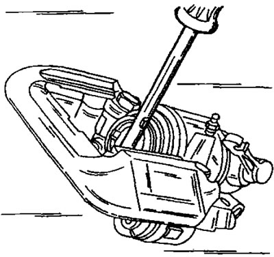
Figure 291. Unscrewing or screwing in the rear wheel brake caliper piston.
13.6.2 Removing and installing the brake caliper
- Remove the brake pads following the instructions section 13.6.
- Unscrew the brake line from the brake caliper.
- Disconnect the handbrake cable.
- Remove the two bolts shown in Figure 290.
- Unscrew the brake hose from the brake cylinder. Place a container underneath to collect the leaking fluid.
The brake caliper is installed as follows:
- Screw on the brake hose and secure the brake line (15 Nm) to the brake caliper. Secure the brake hose to the bracket with a spring bar.
- Open the air bleed valve and wait until the brake fluid starts to flow out. Close the valve.
- Install the cylinder and tighten the bolts to a torque of 120 Nm. Coat the bolt threads with Loctite paste.
- Install the brake pads.
- Lubricate the end of the handbrake cable and connect it to lever 1 in Figure 290.
- After installing the brake caliper, bleed air from the brake system (section (13.7). Bleeding air is easier if you first fill the hose with brake fluid. Finally, check the handbrake adjustment.
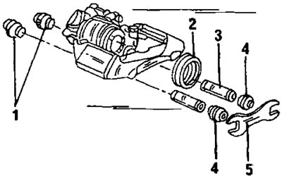
Figure 292. Partially disassembled rear wheel brake caliper. 1. Rubber bushing; 2. Dust ring; 3. Guide sleeve; 4. Rubber bushing; 5. Locking plate
13.6.3 Repair of the brake caliper
- Secure the brake caliper in a vice using soft metal pads.
- Remove the dust ring.
- Release the piston as shown in Figure 291 so that it can rotate freely.
- Place a piece of wood between the piston and the brake caliper and carefully blow out the piston with compressed air.
- Use a blunt object to pull out the sealing ring from the inside of the hole. A blunt feeler gauge can be used for this purpose.
- Clean the parts with alcohol and check the piston and cylinder for wear, scratches and corrosion. If there is any damage, be sure to replace the parts.
- Insert a new seal into the cylinder bore and lubricate the piston and sealing ring with clean brake fluid.
- Insert the piston and then screw it in with a screwdriver as shown in Figure 291 until the mark is in the position shown in Figure 288. This position removes air from the brake caliper and ensures correct installation of the brake pads.
- Install the dust ring.
- If necessary, also replace the parts shown in Figure 292.
13.6.4 Brake discs
- Brake discs assembled with hubs cannot be ground and must be replaced if excessively worn. Wear should not exceed 0.5 mm on each side of the disc. The runout of the brake disc is checked using a dial indicator. To do this, place the dial indicator on the stand so that the dial indicator's feeler gauge rests on the outer side of the brake disc at a diameter of 228 mm. When turning the disc, the dial indicator's needle should not deviate more than 0.07 mm.
- To remove the brake disc, you need to remove the brake pads, unscrew the bolt (1) in Figure 293, after which the disc is removed to the side.
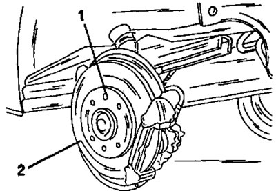
Figure 293. Bolt (1) secures the brake disc (2) of the rear wheel brake to the wheel hub.
The brake disc is installed in reverse order.