



Table of contents: 13.10.1 Brief description 🠇 13.10.2 Removing and installing…🠇 13.10.3 Bleeding the brake system 🠇
13.10.1 Brief description
A Bosch or Bendix system can be installed. The Bendix system is only installed with rear drum brakes. The Bosch system can be installed with both drum brakes and disc brakes on the rear wheels. The system consists of hydraulic and electronic components that work with a conventional braking system. In addition to the additional components, the hydraulic system layout varies, primarily due to the installation of two rigidly mounted brake force regulators in the Bendix system and a load-sensitive brake force regulator in the Bosch system. A knowledgeable reader can follow the brake fluid flow diagram in Figures 297 and 298.
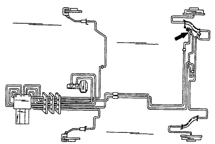
Figure 297. Routing of pipelines for the ABS system manufactured by Bosch (2E) with installed drum brakes on the rear wheels. If there are disc brakes, the scheme is similar. The arrow indicates the location of the brake force regulator.
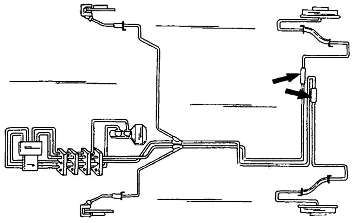
Figure 298. Routing of pipelines for the Bendix ABS system with rear drum brakes installed. The arrows indicate the location of the brake force regulators.
The hydraulic control unit is included in the brake system. The purpose of the control unit is to supply the brakes with fluid as needed.
The electronic components of the system are wheel speed sensors and an electronic control unit. One sensor is installed on each wheel, namely on the steering knuckles for the front wheels and on the axle for the rear wheels. The purpose of the sensors is to measure the wheel rotation speed at certain points in time and transmit the measurement results to the control unit. depending on the information received, the control unit sends control signals to the flaps (electromagnetic valves) hydraulic control units that distribute pressure to the four brakes accordingly.
13.10.2 Removing and installing sensors
- Raise the front or rear of the vehicle after loosening the wheel bolts and remove the wheels.
- Disconnect the cable connection connector and release the cable from the mounting clamps, depending on how it is secured.
- Loosen the sensor mounting bolt and remove the sensor.
- Installation is carried out in reverse order, taking into account the following instructions:
- The front wheel sensors must have a gap between the tip of the sensor and the gear wheel, which is not adjustable.
- The mounting bolt is tightened to a torque of 10 Nm. The bolt threads are lubricated with locking paste.
- Install the wheels, lower the vehicle and tighten the wheel bolts. Maintain the tightening torque of the wheel bolts (85 Nm).
13.10.3 Bleeding the brake system
Bleeding the brake system is done in the same way as on vehicles that do not have an ABS system, with the difference that when installing a Bendix system, the hydraulic control unit has two air release valves in the locations shown in Figure 299.
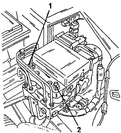
Figure 299. Location of the two air bleed valves (1) and (2) on the installed Bendix system.
Removing air from such a system is done in the manner already described. They start with the wheel cylinder that is farthest from the main brake cylinder, and the last cylinder is the cylinder of the left front wheel.
Now have your assistant press the brake pedal and unscrew the valve (1) in Figure 299. Do not allow the brake fluid to leak out by immediately closing the valve and releasing the brake pedal. Repeat this process until the brake fluid coming out of the valve is free of air bubbles
Repeat this work with the valve (2).
Finally, fill the expansion tank with brake fluid to the required level. Always observe the following precautions:
- During operation, constantly maintain the brake fluid level in the expansion tank at the prescribed level.
- Use fresh brake fluid for topping up. Do not add brake fluid that has already been drained from the brake system.
- Do not spill brake fluid on painted surfaces of the vehicle. In addition, brake fluid is poisonous.
When bleeding air with the Bosch system installed, proceed in the same way as described in section 13.7, but in a different sequence. Air can be removed from both brake circuits independently. For the front brake circuit, start with the left front brake caliper and then bleed the air from the right front brake caliper. Open the valve shown in Figure 300. After removing the air, put the rubber cap back on.
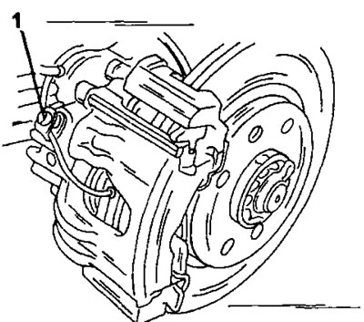
Figure 300. Location of the air bleed valve (1) on the front wheel brake caliper.
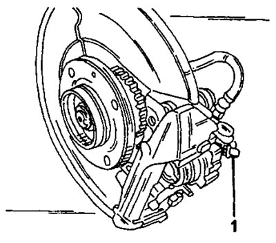
Figure 301. Location of the air bleed valve (1) on the rear wheel brake caliper.
Carry out the same work on the rear left brake caliper, and then on the rear right wheel brake caliper.
If the brakes are generally performing poorly, the entire system should be bled. In this case, carry out the work in the following sequence: rear right, rear left, front left and front right wheel. If necessary, repeat several times.