
This type of reduced length brake master cylinder (88mm compared to 138mm for classic brake master cylinders) allows you to place the following elements:
- extended capacity battery for countries with cold climates;
- automatic transmission computer.
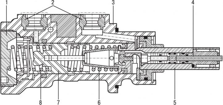
Pic. 8.1. Master brake cylinder: 1 - threaded plug; 2 - connecting sleeves; 3 - body of the main cylinder; 4 - pusher; 5 - primary piston with emergency braking system controls; 6 - piston return spring; 7 - secondary piston; 8 - piston return spring
The peculiarity of the main brake cylinder is that the control elements of the emergency braking system are integrated inside the primary piston (pic. 8.1).
To remove the brake master cylinder:
- remove the decorative battery cover;
- remove the mudguard of the left front wheel arch;
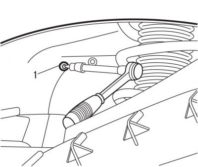
Pic. 5.20. Removing a bolt (1) battery support mountings
- from under the arch of the left front wheel, unscrew the bolt 1 (see fig. 5.20) fastening of a support of the accumulator battery;
- remove the battery;
- remove the battery support;
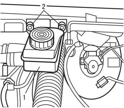
Pic. 8.2. Bolt location (2) compensation tank fasteners (1)
- remove the cover from the compensatory tank 1 (pic. 8.2) with brake fluid
- pump out the brake fluid from the compensation tank with a syringe;
- unscrew the fastening bolts 2 and remove the compensation tank by disconnecting from it the tube connecting it to the lower tank;
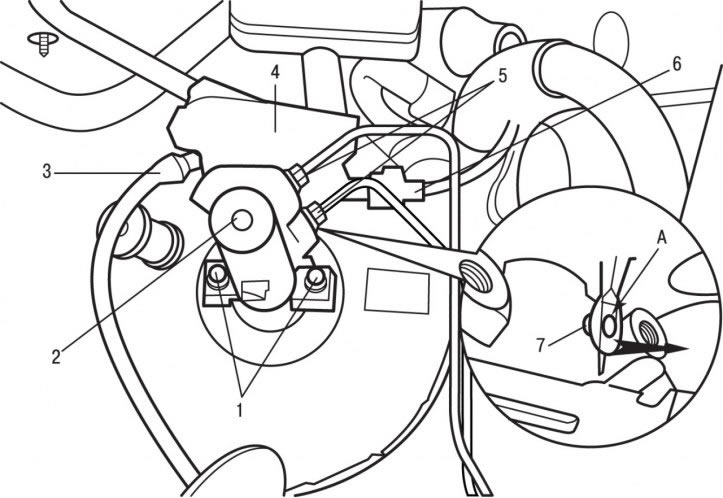
Pic. 8.3. Elements of connection and fastening of the main brake cylinder: 1 - nuts, 20 Nm; 2 - main brake cylinder; 3 - tube of hydraulic clutch drive; 4 - lower reservoir; 5 - connecting nuts, 15 Nm; 6 - electrical connector; 7 - axis; A - fasteners
- disconnect electrical connector 6 (pic. 8.3);
- Drain the brake fluid from the lower tank 4 by moving aside the tube 5 of the hydraulic clutch drive. Close the opening of the clutch drive tube with a plastic stopper;
- turn out connecting nuts 5 and disconnect brake pipes from the main brake cylinder;
- close the openings of the main brake cylinder and brake pipes with plastic plugs;
- turn out nuts 1 of fastening and remove the main brake cylinder 2;
- fix the main brake cylinder in a vice with soft sponges;
- remove the lower tank 4 for the brake fluid by moving the clamps A to the sides;
- remove axle 9.
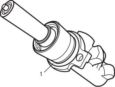
Pic. 8.4. O-ring location (1) master brake cylinder
Installation is carried out in the reverse order of removal, taking into account the following:
Attention! When installing, use a new O-ring 1 (pic. 8.4) master brake cylinder. Check whether the push rod of the brake booster returns freely, the stroke of which is (19,85±1,3) mm (this dimension is determined between the pressure plane of the main brake cylinder and the push rod head).
- remove air from the brake system and hydraulic clutch drive;
- tighten the nuts of the main brake cylinder to 20 Nm;
- tighten the connecting nuts securing the brake pipes to 15 Nm.