



10.1.1. Removal
- Place the front of the car on stands. Remove the front wheels. If there is a repair pit, the wheels do not need to be removed.
- Turn the steering wheel to one side until it stops and unscrew the steering tip nut from the steering knuckle arm.
- Install the ball joint puller in accordance with Fig. 121 and disconnect the joint pin.
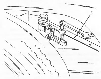
Figure 121. Installing a puller on the steering tip to separate it from the steering knuckle arm.
- Turn the steering wheel all the way to the other side and do the same on the other side.
- From the engine compartment side, loosen the tie rod nut in Figure 122. This tie rod holds the top of the steering shaft in the joint. To disconnect, pull the steering wheel up sharply.
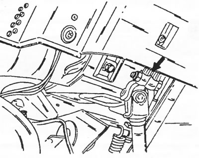
Figure 122. The arrow indicates the location of the crosspiece clamp between the upper and lower steering shafts
- Unscrew the cover bolts under the pedals and pull the cover up together with the rubber seal.
- Loosen the two steering column mounting brackets underneath the vehicle. One of the brackets is located in the location shown in Figure 123. The other mounting bracket is located on the opposite side of the steering column.
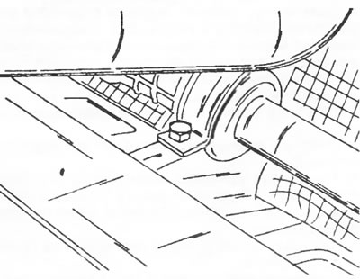
Figure 123. The steering is secured with two mounting brackets on the left and right.
- Pull the steering control out of the vehicle as shown in Figure 124.
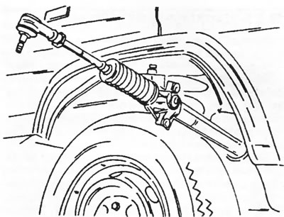
Figure 124. The steering is pulled out and inserted from this side.
If it is necessary to replace the steering tips, loosen the lock nuts and unscrew the joints. In this case, you should count the number of turns required to completely unscrew. Record the number of turns on each side so that you can screw on new tips with the same number of turns later. This maintains the toe-in adjustment.
10.1.2. Installation
The steering control is installed in the reverse order, taking into account the following points:
- Check the condition of the steering cuffs and the reliability of their fastening.
- Tighten the steering mounting bolts to a torque of 50 Nm.
- If new tie rod ends are installed, they should be screwed on as described above. After installation, measure the distance "L" in Figure 125. Adjust this dimension to exactly 322.0 mm. Tighten the lock nut (60 Nm). The length should be checked even if only one tie rod end is being replaced.
(Information posted on the website: www.peugeotbook.ru)
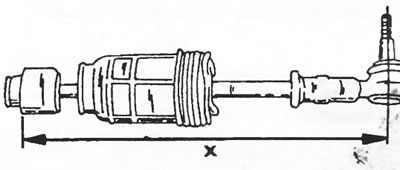
Figure 125. Before installing the steering control, use a measuring ruler to set the value of dimension "X" to the specified value.
- Connect both tie rod end joints and tighten the nuts to a torque of 55 Nm. The ball joints must be degreased.
- Set the steering wheel to the center position. To do this, remove the cuff fastening clamp on the left side and pull the cuff away. After this, rotate the steering wheel so that the dimension shown in Figure 126 is 76.0 mm. Without changing the position of the steering wheel, tighten and secure the cuff.
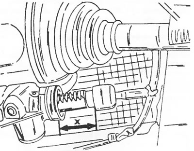
Figure 126 Turn the steering to a position where the "X" dimension value is 76.0 mm.
- Set the steering wheel to the center position and connect the upper and lower crosspieces without changing the position of the steering wheel and steering control. Tighten the tie bolts to a torque of 25 Nm.
- Check and, if necessary, adjust the toe-in as described in section 10.5. Toe-in adjustment is achieved by changing the length of the steering rods.
10.1.3. Steering repair
The steering system cannot be disassembled. If worn or damaged, the steering must be replaced. If there is any shaking in the steering while driving, the rack damper may need to be adjusted. This requires removal of the steering wheel. Provided that there is no other damage to the steering, adjustment is made as follows:
- Clamp the steering in a vice using metal shims, loosen the large lock nut next to the steering gear and turn the adjusting bolt out enough to remove the damper and spring. Clean the parts thoroughly.
- Lubricate the damper and insert it into the housing. Place a spring on top.
- Place the adjusting plug on the spring and screw on the lock nut.
- Tighten the adjusting plug until the damper is pressed against the rack (Figure 127).
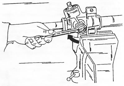
Figure 127. Tighten the adjustment plug of the rack damper until the rack is pressed by the damper.
- After this, unscrew the adjusting plug by 1/8 turn, as shown in Figure 128.
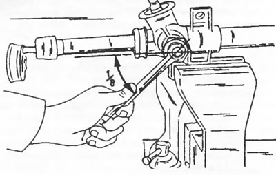
Figure 128. Loosen the adjusting plug in 1/8 turn increments until the rack can move freely.
Take hold of the steering rod and use it to move the toothed rack from stop to stop. The rack must move freely. If rubbing is detected in the movement of the rack, unscrew the adjusting plug by another 1/8 turn until the toothed rack moves freely. Typically, proper adjustment is achieved by loosening the adjustment plug 1/4 to 1/2 turn. If the rack continues to jam after this, it's likely that a foreign object has gotten caught between the damper and the rack. It is best to remove the damper again to inspect the parts. While holding the adjusting plug, tighten the lock nut to a tightening torque of 60 Nm.
Other repairs include replacing steering seals and steering rods. These works are described in section 10.4.