
English Русский
Български
Беларускі
Український
Српски
Hrvatski
Română
Polski
Slovenský
Magyar
Bookmark Articles Sitemap Contacts
Company Hyundai Company Opel Company Skoda Company Kia Company Mitsubishi Company LADA Company Audi
PeugeotBook.ru


Series 100   Series 200   Series 300   400-500   Series 600   Crossovers   Others
 
Peugeot 305 (1977-1989) Peugeot 306 (1993-2002) Peugeot 307 (2001-2008)

Rack and pinion steering mechanism (Peugeot 306)

  • Main
  • 30X
  • Peugeot 306 (1993-2002)
  • Chassis, running gear
  • Steering system
  • Rack and pinion steering mechanism
0
Table of contents: 10.1.1. Removal 🠇 10.1.2. Installation 🠇 10.1.3. Steering repair 🠇

10.1.1. Removal


  • Place the front of the car on stands. Remove the front wheels.
  • From the engine compartment side, loosen the tie bolt nut (2) in Figure 203. This tie bolt holds the steering shaft crosspiece in the pinion.
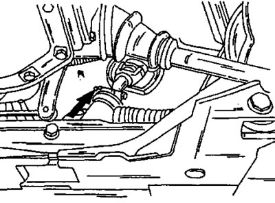
Figure 203. The arrow indicates the tie bolt securing the steering shaft to the gear.
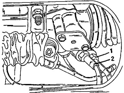
Figure 203. The arrow indicates the tie bolt securing the steering shaft to the gear.


Figure 204. After unscrewing the union nut of the hose (1), the fluid can be drained from the…

Figure 204. After unscrewing the union nut of the hose (1), the fluid can be drained from the hydraulic system. The return hose (2) is located nearby.

  • If equipped with power steering, drain the fluid from the hydraulic system. In this case, the engine must be turned off and the battery disconnected. Unscrew the union nut of the pressure pipe (1) in Figure 204 and pull the hose out of the fitting. Place a flat container under the steering mechanism. Slowly turn the steering wheel from one stop to the other and wait until the fluid flows out. Disconnect the other hose as well.
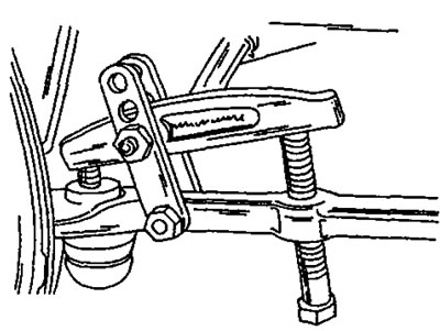
Figure 205. Pressing out the steering tip joint using a special puller.
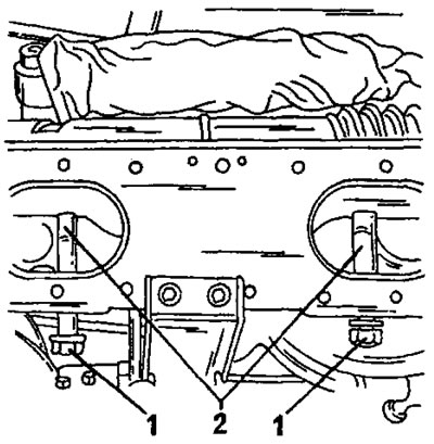
Figure 205. Pressing out the steering tip joint using a special puller.


Figure 206. Location of two mounting bolts (1) of the rack and pinion steering mechanism. Spacers…

Figure 206. Location of two mounting bolts (1) of the rack and pinion steering mechanism. Spacers (2) are inserted between them.

  • Disconnect the three gear shift rods from the levers.
  • Loosen the nuts of the two ball joints of the steering tips and, using the special puller shown in Figure 205, disconnect the connections on both sides.
  • Loosen the bolts and nuts (1) in Figure 206 and remove the spacers (2).
  • Rotate the steering gear around its axis and pull it out through the wheel arch.
  • If it is necessary to replace the steering tips, loosen the lock nuts and unscrew the joints. In this case, you should count the number of turns required to completely unscrew. Record the number of turns on each side so that you can screw on new tips with the same number of turns later. This maintains the toe-in adjustment.

10.1.2. Installation


The steering control is installed in the reverse order, taking into account the following points:
  • Check the condition of the steering cuffs and the reliability of their fastening.
  • If new tie rod ends are installed, they should be screwed on as described above. If new steering rods are installed, replacement is carried out in accordance with the instructions in section 10.4.
  • Set the steering control to the center position in accordance with section 10.3.
  • Place the steering gear onto the front crossmember while simultaneously inserting the steering gear into the steering wheel flange. Check the correct position of the steering wheel spokes. If the position is incorrect, turn the steering shaft half a turn.
  • Place spacers and insert both mounting bolts.
  • Install new self-locking nuts and tighten both nuts alternately to a torque of 50 Nm.
  • Drive the tie bolt into the location shown in Figure 203. The recess on the shaft must match accordingly. Tighten the new self-locking nut to 25 Nm.
  • Connect the steering tips to the steering arms. For secure fastening, the ball joints must be degreased. Tighten the new self-locking nuts to 35 Nm.
  • Fill the hydraulic system with fluid and bleed air from the system in accordance with the instructions in Section 10.6.
  • Check and, if necessary, adjust the toe-in as described in section 10.5. Toe-in is adjusted by changing the length of the steering rods.


10.1.3. Steering repair


The steering system cannot be disassembled. If worn or damaged, the steering must be replaced. Although the rack and pinion damper can be adjusted, it is recommended that this work be performed by a service station as it requires a special dial indicator and an additional steering damper cover. Adjustment requires drilling a hole in the cover, so it cannot be installed after the work is completed.

The power steering cylinder can be replaced separately in accordance with Figure 207. The cylinder is bolted to the rack on one side and secured to the steering rod on the other side with a nut. Tightening torques are shown in Figure 207.
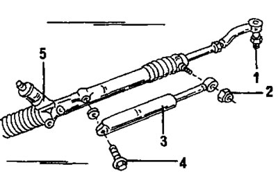
Figure 207. Fastening the power steering cylinder. 1. Bolt, 55 Nm; 2. Nut, 55 nm; 3. Power steering…

Figure 207. Fastening the power steering cylinder. 1. Bolt, 55 Nm; 2. Nut, 55 nm; 3. Power steering cylinder; 4. Tie rod hook, 35 Nm; 5. Rack and pinion steering gear housing
This article is available at russian, bulgarian, belarusian, ukrainian, serbian, croatian, romanian, polish, slovak, hungarian
Article reviewed by editor: Shirokov Arseny
Share information:
Previous
Peugeot 306: Steering system
Next

Steering — general description
Central steering position
Replacing the power steering pump drive belt
Replacing zero rods
Wheel alignment angles
See similar information for other Peugeot models

➨ Steering and suspension check Peugeot 106 (1991-2003)
➨ Executive mechanism (power steering electric pump unit) Peugeot 207 (2006-2014)
➨ Steering wheel, gear shift and brake Peugeot 405 (1987-1997)
➨ Steering wheel Peugeot 605 (1989-2000)
➨ Rack and pinion steering Peugeot J5 (1981-1993)
Link to this article in different formats
Comments and feedback from visitors
No comments yet


Add two numbers 40 + 29


Peugeot 307 (2001-2008) 
  • User manual
  • Keys, doors and alarm
  • Controls and instruments
  • Driving and operation
  • Maintenance
  • Power unit
  • Petrol engines TU3 and TU5
  • Petrol engines EW10
  • Diesel engines DV10
  • Diesel engines DW10
  • Transmission
  • Clutch and drive shafts
  • Mechanical gearbox
  • Automatic gearbox
  • Chassis, running gear
  • Front suspension
  • Rear suspension
  • Steering
  • Brake system
  • Body and interior
  • Exterior (external elements)
  • Interior (internal elements)
  • Doors, locks and windows
  • Heating and air conditioning
  • Electrical equipment
  • Equipment and devices
  • Power devices
  • Airbags
  • Electrical circuits
Peugeot 306 (1993-2002) 
  • General information
  • Introduction to manual
  • Specifications
  • Gasoline engine
  • Engine repair
  • Lubrication system
  • Cooling system
  • Fuel injection
  • Ignition system
  • Diesel engine
  • Engine repair
  • Lubrication system
  • Cooling system
  • Fuel injection
  • Transmission
  • Clutch
  • Gearbox
  • Drive shafts
  • Chassis, running gear
  • Steering system
  • Front suspension
  • Rear suspension
  • Brake system
  • Electrical equipment
  • Power devices
  • Electrical circuits
Peugeot 305 (1977-1989) 
  • General information
  • Maintenance
  • Power unit
  • Gasoline engines
  • Diesel engines
  • Cooling system (gasoline)
  • Cooling system (diesel)
  • Fuel system (gasoline)
  • Fuel system (diesel)
  • Ignition system
  • Transmission
  • Clutch
  • Mechanical gearbox BB8
  • Mechanical gearbox BE1
  • Automatic gearbox ZF4
  • Shafts, hubs and wheels
  • Chassis, running gear
  • Brake system
  • Car suspension
  • Steering
  • Body and interior
  • Exterior (external elements)
  • Interior (internal elements)
  • Electrical equipment
  • Equipment and devices
  • Headlights and lighting
  • Power devices
  • Electrical circuits
  • Wiring diagrams (diesel)
PeugeotBook.ru © 2018–2026 | Mobile version | Sitemap: EN BG BY UA RS HR RO PL SK HU | Write message | Site search | Add to bookmarks | Peugeot owners
106 (1991-2003) | 206 (1998-2012) | 207 (2006-2014) | 305 (1977-1989) | 306 (1993-2002) | 307 (2001-2008) | 405 (1987-1997) | 406 (1995-2004) | 605 (1989-2000) | Partner-I (1996-2008) | Eurovans-807 (2002-2014) | Eurovans-806 (1994-2002) | J5 (1981-1993) |
Cookies are used to ensure the correct display of pages on the site.