



Table of contents: 10.5.1. Longitudinal inclination of…🠇 10.5.2. Collapse 🠇 10.5.3. Front wheel alignment 🠇
Adjustment of the front wheels is carried out with the vehicle under operational load, that is, the vehicle must be unloaded and filled with fuel, oil and water.
To meet the prescribed load conditions, measure the height from the level floor to the front body support under the jack. This dimension should be 143 mm. If 165/170 R14 tires are installed, the required dimension should be 163 mm.
10.5.1. Longitudinal inclination of the kingpin
The longitudinal inclination angle of the kingpin is not adjustable. The angle is measured with a conventional measuring instrument in accordance with the instrument manufacturer's instructions. In addition, there are differences depending on the presence of power steering. The exact values are contained in the tables of adjustments and sizes. If the measured values differ from those given in the tables, it can be assumed that there is a skew in the front wheel suspension. In this case, it is necessary to check all front wheel alignment angles.
10.5.2. Collapse
The camber angle is measured with a conventional measuring instrument in accordance with the instrument manufacturer's instructions. The camber of both wheels should not differ by more than 30'. The camber should be 0°20' with or without power steering. A deviation of 30' in either direction is allowed. The camber is not adjustable. If the measured values differ from the specified ones, it can be assumed that the front suspension is warped. In this case, a check on an optical stand is required, since this is the only way to establish accurate values.
10.5.3. Front wheel alignment
Front wheel toe can be measured with a mechanical toe gauge. The wheels must have either negative toe-in (if equipped with power steering), or positive convergence (in the absence of power steering), that is, the front sides of the wheels should be located closer to each other than the rear ones. The measurement is carried out as follows:
- Check and, if necessary, adjust the tire pressure.
- Place the vehicle on a level surface and set the wheels to point straight ahead. This can be done using the spokes of the steering wheel.
- Place the measuring rod on the front side of the wheels and place both measuring pins on the edges of the rims, setting the rod scale to zero. This is done at the level of the wheel hubs.
- Mark the contact points of the measuring pins with chalk.
- Remove the measuring rod.
- Move the car forward by half a turn of the wheels, that is, both chalk marks should be on the rear side of the wheels at the level of their hubs.
- Place the measuring rod under the vehicle and attach the measuring pins to the rims. If the wheels have positive toe-in, the pins should be pulled out of the rack.
- Place the pins and read the scale readings. The size should be either -1±0.5 mm on vehicles with power steering, or +1±0.5 mm if there is power steering.
- If this is not the case, loosen the lock nuts on both tie rods at the outer ball joints and change the length of the tie rods to the same value. Change the length in small portions and measure the toe-in each time. It should be taken into account that the visible section of the thread between the steering tip and the nut on both sides should be the same with an accuracy of approximately 2.0 mm (figure 210).
- Finally, tighten both locknuts to a torque of 44 Nm. While doing this, hold the steering rods from turning. To prevent the cuffs from twisting when turning the steering rods, you need to release their fastening from the outside.
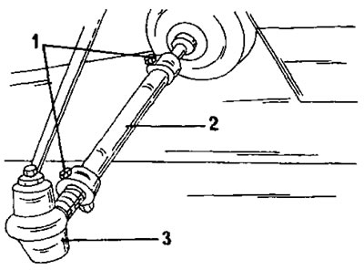
Figure 210. Adjusting the toe-in 1. Nut; 2. Steering rod; 3. Steering tip