



There are two types of repairs that can be performed on drive shafts: replacing the rubber seals and replacing the constant velocity joint on the wheel side.
When deciding whether to replace either the seal or the joint, be aware that the joint is very tightly fitted to the shaft and requires an impact puller to remove it. The impact puller is a weight that can move on a rod, which is struck against an external stop, thereby removing the hinge. In this case, the impact puller must be installed on the threaded part of the drive shaft. Service stations use a threaded sleeve that is screwed into the shaft at one end and into the impact puller at the other end. The same goal can be achieved by screwing on the shaft nut and applying an impact puller to it. In this way, replacement can be made. Figure 116 shows the assembled drive shaft. Numerical references in the following text refer to this figure.
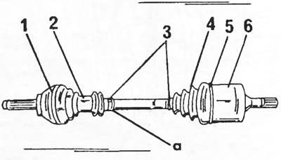
Figure 116. Drive shaft with the location of the parts mentioned in the text. 1. Cuff tightening tape (outer hinge); 2. Rubber cuff; 3. Cuff tightening straps; 4. Cuff, inner hinge; 5. Cuff tightening tape (internal hinge); 6. Inner constant velocity joint; a = Ventilation sleeve
- Clamp the shaft in a vice and remove the clamping bands of cuffs 1, 3 and 5.
- Place the impact puller against the end of the joint thread and strike it outward with the weight until the joint comes off the shaft. The working operation is shown in Figure 117. You can also try hitting the hinge from behind with a plastic hammer.
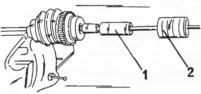
Figure 117. Using an impact puller. A threaded sleeve (1) is screwed onto the end of the drive shaft and onto the rod of the impact puller. The hinge comes off the shaft when the weight (2) of the impact puller strikes backwards.
- Remove both seals from the shaft.
- Remove the retaining ring shown in Figure 118 from the shaft.
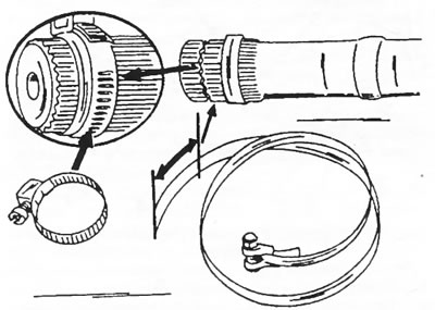
Figure 118. Removing and installing the fastening ring on the splined part of the shaft.
If only the hinge needs to be replaced, it is sufficient to remove the mounting clamps (1) and (3) and knock down the hinge using the method described above.
The rubber seal on the gearbox side can be replaced after removing the joint shown in Figure 119 (generally only on cars produced after September 1990). The hinge is secured with a retaining ring.
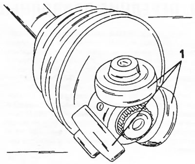
Figure 119. Constant velocity joint. Three bearings (1) of the hinge move freely along the bearing journals.
The cuffs are supplied complete with grease, which is added during assembly. The shaft assembly is carried out as follows:
- Pull the rubber seals (2) and (4) onto the shaft and install the bushings.
- Place the constant velocity joint on the shaft using Figure 117. The joint is also mounted using an impact puller. However, first you should study Figure 118. Place a new retaining ring on the shaft and put the clamp on it, but do not close it completely (fragment in figure 118). Now you can hammer the joint until the retaining ring slips into the groove of the shaft.
- Fill the cuff (2) and the joint with grease and put the cuff on. Install the bushing at location "a" in Figure 116.
- Secure the cuff with new tie straps.
- If the joint sprocket was removed, pull the cuff onto the shaft and put the joint sprocket onto the shaft. Secure the retaining ring in front of the hinge.
- Fill the bearings of the joint in Figure 119 with grease and place them on the journals of the joint sprocket.
- Spread the grease supplied in the repair kit evenly from three bags over the inside of the hinge (6) in Figure 116 and the cuff (4) and mount the hinge (6).
- Place the rubber cuff on and secure with the straps (3) and (5). Ensure the straps are securely fastened.
Original published on the portal (PeugeotBook.ru)