



The wheel hub cap may be damaged during removal. At the service station, a special puller is used to remove this cap.
Removal of the left and right drive shafts is carried out as follows:
- Apply the handbrake and engage first gear.
- Loosen the wheel nuts, raise the car and place it on stands.
- Using a thin chisel, knock off the cap in various places around the circle between the cap and the wheel hub. Be careful not to damage the cap.
- Screw the wheel back on and lower the car to the ground.
- Bend back the locking tab on the drive shaft nut and loosen the nut.
- Place the car back on the stands. In this case, the steering knuckles should sag. Remove the wheel and unscrew the drive shaft nut.
- Using Figure 112, unscrew the two bolts (3) securing the suspension ball joint and the bolts (1) securing the steering knuckle arm.
- Press the entire steering knuckle (2) outward. Move the transverse arm down until the ball joint is released. Pull the steering knuckle further outward until the drive shaft exits the steering knuckle.
- Loosen the drain plug on the gearbox and drain about 1 liter of oil into a clean container. This will prevent any oil from leaking out of the gearbox. Naturally, you can drain all the oil from the gearbox.
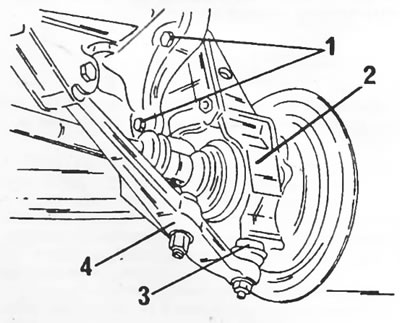
Figure 112. When removing the right drive shaft, release the following parts. 1. Steering knuckle arm bolts; 2. Steering knuckle; 3. Suspension ball joint; 4. Wishbone
When removing the right drive shaft
The technology for removing the shaft depends on the model and mounting method.
- On cars with gasoline engines produced before approximately March 1983, the drive shafts are pulled outward (not all three car manufacturers introduced the new shaft modification at the same time).
- On all other vehicles, as well as vehicles with petrol engines manufactured after March 1983, the drive shafts are removed using Figure 113. To release the outer bearing ring, loosen the nuts (1) and unscrew the bolts (4) half a turn.
- Unscrew the three support bearing bolts from the cylinder block and pull out the shaft.
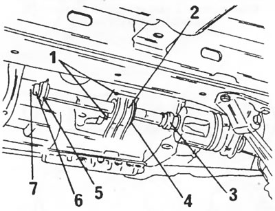
Figure 113. Removing and installing the right drive shaft.1. Nuts; 2. Shaft support bearing; 3. Bearing ring; 4. Tie bolts; 5. Anther; 6. Ring; 7. Round section seal
When removing the left drive shaft
- Place a chisel between the constant velocity joint housing and the drive bolt, as shown in Figure 114. Check the chisel installation again and carefully tap the end of the chisel (arrow 1) with a hammer. Once the shaft is felt to be free, tap the chisel with a hammer in the direction of the arrow (inside the hammer) until the shaft disengages from the gearbox.
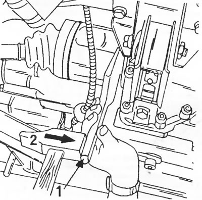
Figure 114. Removing the left drive shaft. To release the drive shaft from the gearbox, first hit the chisel with a hammer in direction (1), and then in direction (2).
- Grasp the control arm as shown in Figure 115 and pull it down while simultaneously pushing the wheel up and out. Remove the drive shaft from the gearbox.
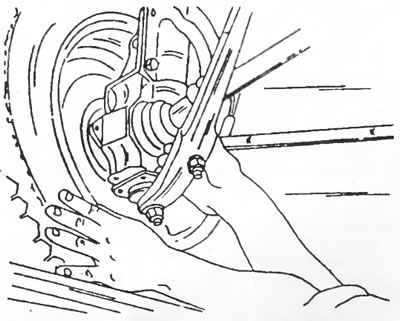
Figure 115. Pull the wishbone down, pushing the wheel outward. At the same time, the drive shaft comes out of the gearbox.