
Note. If a new electronic control unit is to be installed (BEU), have this work done by a Peugeot/Citroen dealer. After installing a new BEU, it is necessary to perform its initialization procedure, which requires the use of special diagnostic equipment.
Release models prior to September 2002
25. BEU is located in a plastic box, which is part of the rear section of the battery shelf. On some engines, access to the nuts/bolts securing the BEU is difficult, and it is recommended to first remove the battery shelf, as described in chapter 5A, and then on the workbench remove the BEU from the shelf.
26. Disconnect the ground wire from the battery (see «Disconnecting the battery»).
27. If applicable, remove the cover from the BEU, and then lift the locking latches and disconnect the electrical connectors of the BEU (pic. 13.27).
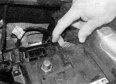
Pic. 13.27. Raise the locking latches and disconnect the electrical connectors of the LCU (early models)
28. Turn away nuts or turn out bolts and remove the BEU support plate from the battery shelf.
29. Turn away nuts or turn out bolts and separate BEU from a basic plate.
30. Installation is carried out in the reverse order of removal. Connect electrical connectors securely.
Release models after September 2002
31. The BEU is located in the left rear corner of the engine compartment, above the upper support of the suspension strut.
32. Disconnect the ground wire from the battery (see «Disconnecting the battery»).
33. Remove the nuts and remove the BEU cover, if applicable (pic. 13.33, a, b).
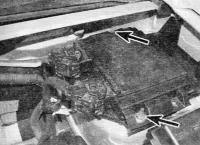
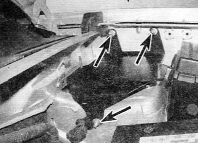
Pic. 13.33 a.m. Loosen the nuts (marked with arrows)...
Pic. 13.33 b....and remove the BEU cover (later models)
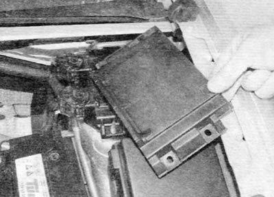
34. Raise the BEU and remove it from the support bracket, and then lift the locking latches and disconnect the electrical connectors (pic. 13.34).
Pic. 13.34. Remove the BEU from the support bracket, and then disconnect the electrical connectors (later models)
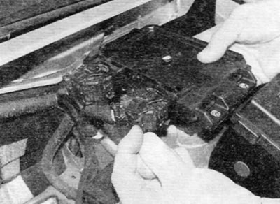
35. If necessary, after unscrewing the three fastening nuts, you can remove the support bracket (pic. 13.35).
Pic. 13.35. BEU support bracket mounting bolts (marked with arrows) (later models)
36. Installation is carried out in the reverse order of removal. Connect electrical connectors securely.