
Manifold pressure sensor
41. The manifold pressure sensor is mounted on the front of the intake manifold.
42. Disconnect the ground wire from the battery (see «Disconnecting the battery»).
43. Disconnect the electrical connector, then remove the screw and remove the sensor from the manifold (pic. 13.43).
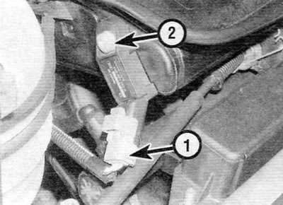
Pic. 13.43. Disconnect the manifold pressure sensor electrical connector (1), and then remove the screw (2) (model shown with 1.4L engine)
44. Installation is carried out in the reverse order of removal. Make sure the sensor seal is in good condition.
Coolant temperature sensor
45. The coolant temperature sensor is screwed into the coolant distribution housing at the left end of the cylinder head. For details on installation and removal, see chapter 3.
Air intake temperature sensor
Note. On 1.4L engine models with the Sagem S2000 system and all 7.6L engine models, the air intake temperature sensor is an integral part of the throttle body and cannot be removed.
46. The air intake temperature sensor is mounted on the base of the throttle body. On early models, the sensor is screwed into a threaded hole on the underside of the throttle body, while on later models it is clamped in place.
47. Disconnect the ground wire from the battery (see «Disconnecting the battery»), then disconnect the sensor electrical connector (pic. 13.47).
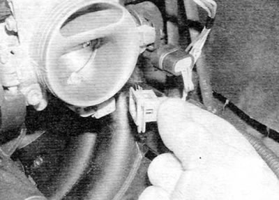
Pic. 13.47. Disconnect the electrical connector...
48. Unscrew the sensor or release the clamps and release the sensor from the throttle body (pic. 13.48).
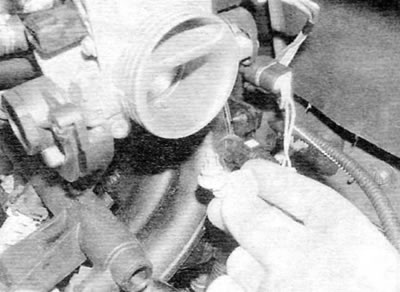
Pic. 13.48....then release the air intake temperature sensor from the clip on the throttle body (models with 1.4 l engine)
Tip: The air intake temperature sensor clamps can be released by passing a tight ring wrench over the end of the sensor.
49. Installation is carried out in the reverse order of removal. Make sure the sensor seal is in good condition.
Crankshaft sensor
50. The crankshaft sensor is located on the front side of the clutch housing.
51. Disconnect the ground wire from the battery (see «Disconnecting the battery»).
52. Disunite an electric socket of the gauge and release electroconducting. Turn out a bolt and remove the gauge in gathering with an arm from a transmission (pic. 13.52, a, b).
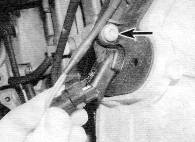
Pic. 13.52 a. Disconnect the electrical connector and remove the screw (marked with an arrow)...
Pic. 13.52 b....then remove the crankshaft position sensor from the front of the clutch housing
53. Installation is carried out in the reverse order of removal.
Throttle Body Heating Element
Note. The heating element is only used on the aluminum throttle body. The plastic housing does not require a heating element.
54. The heating element is located on top of the throttle body.
55. Disconnect the ground wire from the battery (see «Disconnecting the battery»).
56. Disconnect the electrical connector, and then remove the screw and remove the heating element from the throttle body (pic. 13.56, a, b).
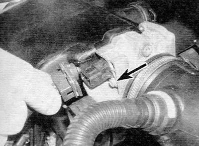
Pic. 13.56 a. Disconnect the electrical connector, and then remove the screw (marked with an arrow)...
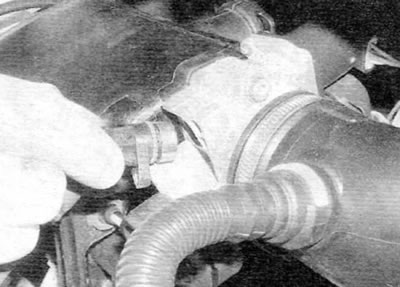
Pic. 13.56, b....and remove the heating element from the throttle body (models with 1.4 l engine)
57. Installation is carried out in the reverse order of removal.
Vehicle speed sensor
58. The vehicle speed sensor is an integral part of the speedometer. For details on installation and removal, see chapter 7.
Knock sensor
59. The knock sensor is screwed into the rear of the cylinder block. For details on installation and removal, see chapter 5B.
Inertial fuel switch
60. The inertial fuel supply switch is located in the right rear corner of the engine compartment.
61. Disconnect the ground wire from the battery (see «Disconnecting the battery»).
62. Cut the clip (if applicable), then remove the nuts and remove the switch from the vehicle by disconnecting the appropriate electrical connector.
63. Installation is carried out in the reverse order of removal. Finally, reset the switch by pressing the top button.
Camshaft position sensor
Note. The camshaft position sensor is available only on models with a 1.4 liter engine with the Motronic MP7.3 system.
64. The camshaft position sensor is located on the rear of the coolant distribution housing at the left end of the cylinder head.
65. Disconnect the ground wire from the battery (see «Disconnecting the battery»).
66. Disconnect the electrical connector, and then unscrew the bolt and remove the sensor from the housing.
67. Installation is carried out in the reverse order of removal. Make sure the sensor seal is in good condition.
Body Accelerometer
Note. The accelerometer is available only on models with a 7.4 liter engine with the Motronic MP7.3 system.
68. The body accelerometer is located in the engine compartment. To remove it, first disconnect the ground wire from the battery (see «Disconnecting the battery»).
69. Disunite an electric socket, then turn out a bolt and remove the gauge from the car.
70. Installation is carried out in the reverse order of removal.
Electric motor of the throttle actuator
71. Throttle actuator motor is available on 1.4L engine models with Sagem S2000 system and all models with 1.6L engine. It is integrated with the throttle body and is not available separately.
Accelerator pedal position sensor
Note. The accelerator pedal position sensor is only available on 14L engine models with the Sagem S2000 system and all models with 7.6L engine.
72. The accelerator pedal position sensor is located above the right engine / gearbox mount (pic. 13.72).
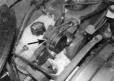
Pic. 13.72. Accelerator pedal position sensor location (marked with an arrow)
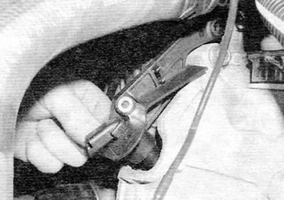
73. Disconnect the ground wire from the battery (see «Disconnecting the battery»), and then disconnect the pedal position sensor electrical connector.
74. Disconnect the accelerator cable from the accelerator pedal position sensor cam, and then pull the cable sheath out of the rubber bushing of the support bracket. Remove the spring clip from the cable sheath.
75. Remove the two support bracket mounting bolts and remove the pedal position sensor and support bracket from the engine compartment.
76. Turn away two nuts and turn out bolts of fastening of the gauge to a basic arm and separate these elements from each other.
77. Installation is carried out in the reverse order of removal. Finally, adjust the accelerator cable as described in paragraph 3.