
General information
1. On early models, the exhaust system consists of four sections: front pipe, catalytic converter, intermediate pipe and center silencer, and rear pipe with rear silencer. All sections are connected by means of flange connections. The downpipe is fixed using nuts and bolts, the catalytic converter has clamps using spring-loaded balls (which allows some mobility of the exhaust system). The connections between the catalytic converter and the intermediate pipe and between the intermediate pipe and the muffler are fixed with a clamping ring.
2. On later models, the exhaust system consists of three sections: a front pipe with an integrated catalytic converter, an intermediate pipe and a center silencer, and a rear pipe with a rear silencer. The suction and intermediate pipes are connected by means of a flange connection. All other connections are fixed with clamping rings.
3. The entire length of the system is suspended by rubber mounts.
Removing
4. Each section can be removed individually or, alternatively, the entire system can be removed. Even if only one part of the system needs attention, it is often easier to remove the entire system and separate the sections on a workbench.
5. To remove the system or part of the system, first raise the front or rear of the vehicle and securely support it under it (see «Lifting and placing the car on supports»). Alternatively, park the vehicle over a pit or raise it onto a flyover.
Downpipe
Note. On later models, the catalytic converter is integrated with the downpipe.
6. Trace the oxygen sensor wiring from the sensor to its electrical connectors, which are secured to the transmission case, and disconnect the connectors by disconnecting the wiring from the main wiring harness.
7. Turn away nuts of flange connection of a reception pipe to a collector and turn out one bolt of fastening of a reception pipe to a corresponding basic bracket (pic. 16.7). Disassemble the flange connection and remove the gasket.
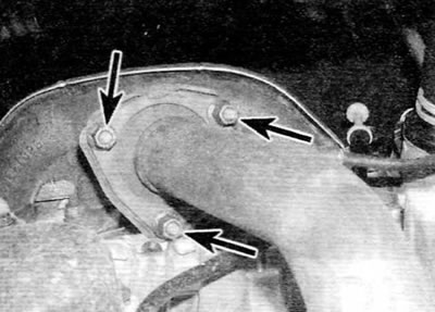
Pic. 16.7. Nuts of fastening of a reception pipe to a collector (marked with arrows) (early models)
8. Turn away two nuts of fastening of flange connection of a reception pipe to catalytic converter or an intermediate pipe and remove caps of springs and springs. Turn out bolts, then take a reception pipe from under the car and remove a laying from a wire grid.
Catalytic converter (early models)
Note. On later models, the catalytic converter is integrated with the downpipe.
9. Turn away two nuts of fastening of flange connection of a reception pipe to catalytic converter. Remove the springs and spring caps and remove the bolts.
10. Loosen the catalytic converter clamp ring bolts and remove the clamp from the flange connection.
11. Release the converter, and then remove it from under the car. Remove the wire mesh pad from the front pipe joint.
Intermediate pipe
12. On later models, unscrew the two nuts on the flange connection between the front pipe and the intermediate pipe and remove the spring caps and springs (pic. 16.12). Remove the bolts and then remove the downpipe from under the car and remove the wire mesh pad.
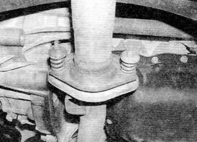
Pic. 16.12. Spring-loaded flange connection between downpipe and intermediate pipe (later models)
13. Loosen clamp ring bolts and remove clamp (-s) with flange connections) (pic. 16.13).
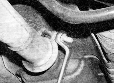
Pic. 16.13. Unscrew the nut, remove the washer and remove the bolt, and then remove the clamp ring from the flange connection
14. Release an intermediate pipe from the corresponding rubber support and take it from under the car.
Rear pipe
15. Loosen the rear pipe clamp ring bolts and remove the clamp from the flange connection.
16. Release a back pipe from the corresponding rubber support and remove it from the car.
Complete system
17. Disconnect the electrical connectors for the oxygen sensors in the main wiring harness.
18. Turn away nuts of fastening of flange connection between a reception pipe and a collector and one bolt of fastening of a reception pipe to a corresponding basic arm. Disassemble the flange connection and remove the gasket. Release the system from all rubber supports and remove it from under the vehicle.
Heat shield (-s)
19. The heat shields are attached to the underside of the vehicle with various nuts and bolts. Each screen can only be removed after the corresponding section of the exhaust system has been removed. If the screen is removed to gain access to the elements located behind it, in some cases it may be sufficient to unscrew the nuts and / or bolts and simply lower the screen without touching the exhaust system.
Installation
20. Each section is installed in the reverse order of removal, taking into account the following points:
- A) Remove all traces of corrosion from the flanges and replace any necessary gaskets.
- b) Inspect rubber mounts for signs of damage or deterioration and replace if necessary.
- V) Before assembling the spring-loaded connection, apply high-temperature grease to the mating surfaces of the connection.
- G) If a clamp ring is used in the joint, apply exhaust system assembly paste to the flange joint to ensure a gas-tight joint. Tighten the clamp ring nuts evenly and progressively so that the gap between the clamp sections is equal on both sides.
- d) Before tightening the exhaust system bolts/nuts, make sure that all rubber mounts are properly positioned and that there is sufficient clearance between the exhaust system and the bottom of the vehicle.
- e) Make sure that the electrical connectors of the oxygen sensors are properly docked, and that the electrical wiring is fixed to the bottom with the appropriate clips.