Table of contents: Logical interface 🠇 Fuses 🠇 Location of connectors 🠇 Electrical connector contacts…🠇 EP connector 🠇 EA connector 🠇 EH1 connector 🠇 PH1 connector 🠇 PH2 connector 🠇 PP connector 🠇 PB connector 🠇 PB1 connector 🠇 AP connector 🠇
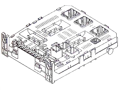
The switching unit (BSI 1) is the main unit in the electrical equipment system with multiplex communication. The unit includes a mechanical interface, an electronic board based on microcontrollers and a logical interface, which perform the following functions:
- switching between different multiplex circuits;
- switching between circuits formed by wires and multiplex circuits;
- diagnostics;
- receiving information from sensors;
- distribution and protection of power supply to elements associated with the BSI 1 unit;
- management of multiplex communication dialogue protocols.
Logical interface
The software interface initiates the launch of BSI 1, controls the microcontroller that performs the functions of an intelligent switching unit, and provides remote loading of software (drivers) designed to implement various functions of the CAN DIAGNOSTIC network:
- windshield wiper and washer relay control;
- direction indicator time delays;
- various lighting devices;
- exchange of information with various networks Can, can comfort, Can car, CAN COMMUTE (switchable).
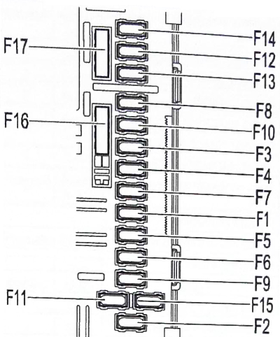
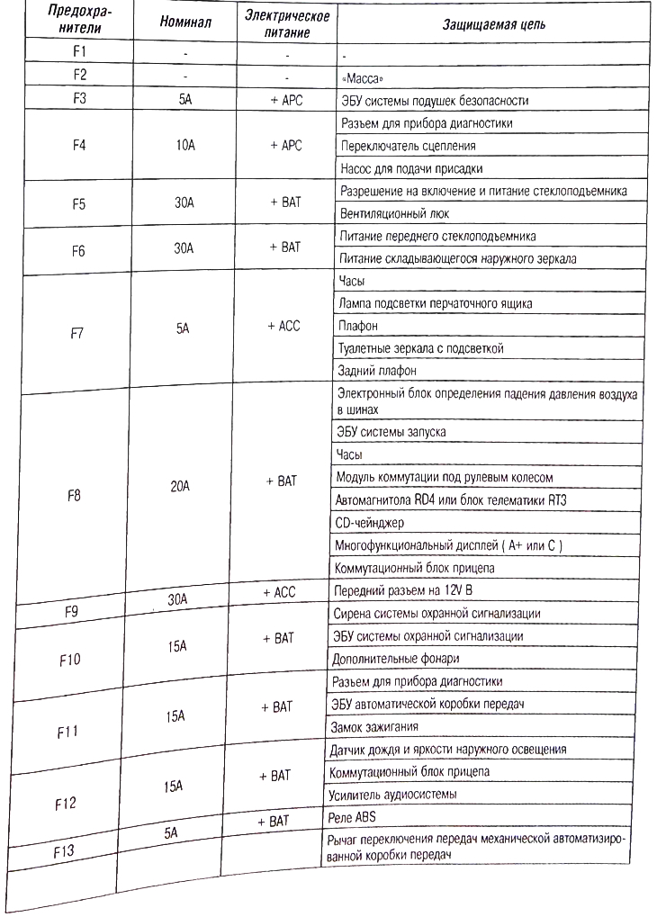
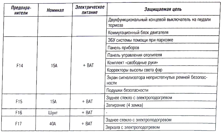
Fuses
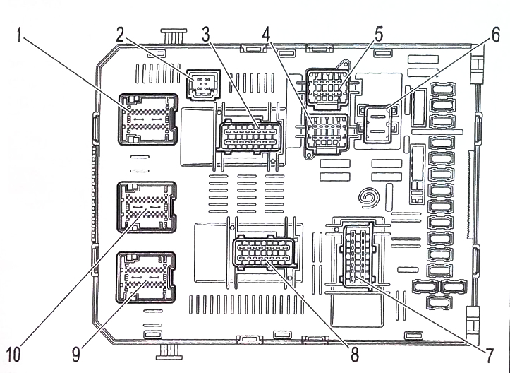
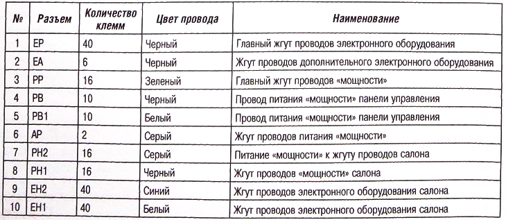
Location of connectors
(Data published on the website: «peugeotbook.ru»)
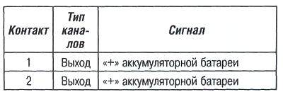
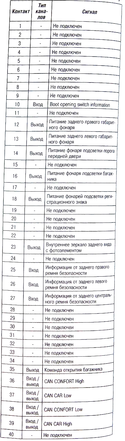
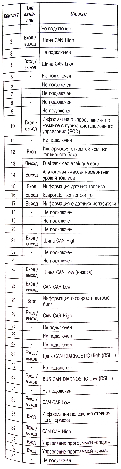
Electrical connector contacts assignment (connector EH2)
EP connector
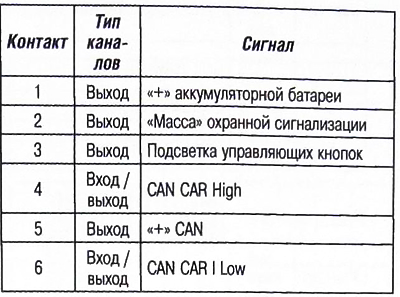
EA connector
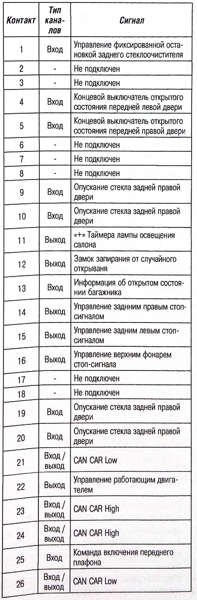
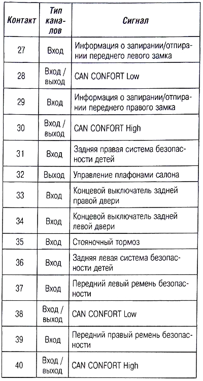
EH1 connector
PH1 connector
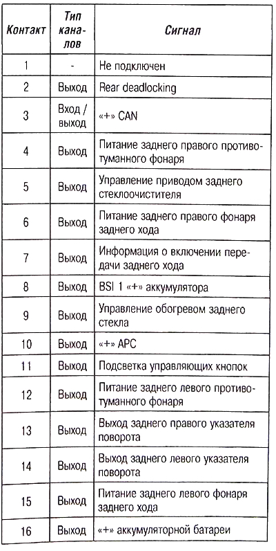
PH2 connector
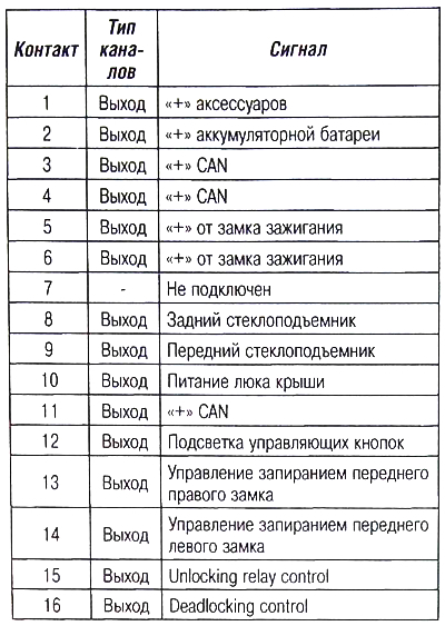
PP connector
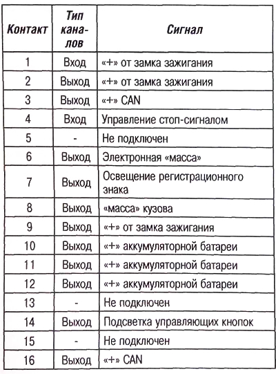
PB connector
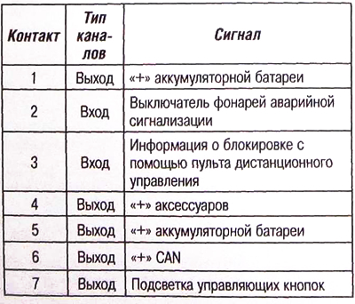
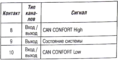
PB1 connector
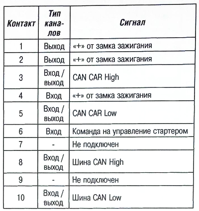
AP connector