



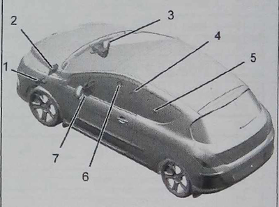
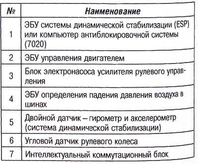
Location of the CAN IS network ECU
The CAN IS network connects control units related to vehicle movement, such as the brake system, gearbox or engine.
Data transfer rate 500 Kbps (High Speed).
The CAN network is a network of many units, where each unit continuously transmits information to all other units.
Each ECU processes its own information.
Messages are transmitted over the network periodically, except for messages of a random nature. The CAN IS network has a device that allows communication to be established when at least two control units are included in it.
The engine management ECU (1320) and the electronic control unit (BSI 1) are the only computers that have a terminating resistor.
To ensure network communication, the engine control unit (1320) and the switching unit (BSI 1) must always be online.
Features of the CAN IS network:
- some control units are connected in a line activated by a command from a remote control (RDC), which allows the control units to be pre-"woke up";
- diagnostic line K.
Note: A break in the CAN High or CAN Low wire will prevent communication on the network.
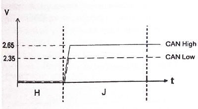
Designations:
- "N" - CAN network in standby mode;
- "J" — CAN network in working mode;
- "V" — volt;
- "T" is for time.
The CAN intersystem network is characterized by two average voltage values in operating mode:
- Can High - 2.65V;
- CAN Low — 2.35V.
The CAN network is in operating mode when CAN IS High + CAN IS Low = 5V.
Note: The voltage values shown are average values.
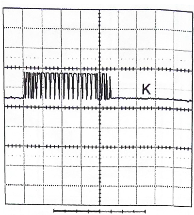
CAN network nominal curves (oscilloscope readings)
 |
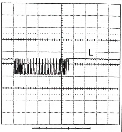 |
- "K": CAN High;
- "L": CAN IS Low.
Voltage: 1V.
Time: 100 m/s.
Test conditions:
- the engine is not working;
- ignition is on.
Results: Observe a DC component at approximately 2.5 volts and a series of AC pulses with an amplitude of 1 volt, representing the information transmitted over the CAN network.
The CAN Low signal has the opposite direction compared to the CAN High signal.