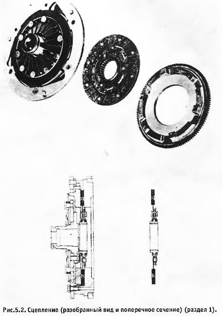
The driven clutch disc is on the splines of the drive gear of the gearbox and can move freely between the surfaces of the flywheel and the pressure plate. Double friction linings on the outer side of the disc are attached to the internally splined hub with 6 spring dampers that dampen the initial jerk when the clutch is engaged.
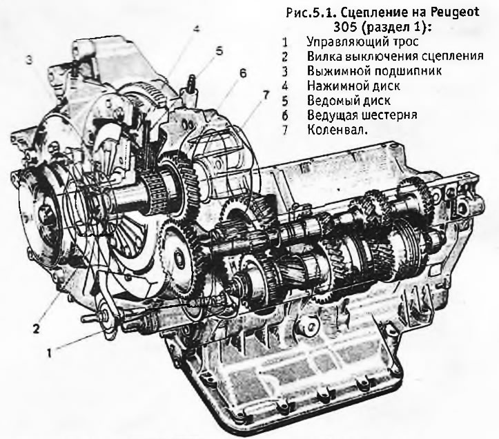
The drive gear rests on the crankshaft, from which it is separated by a double-row needle bearing. The clutch is on the outside of the pinion gear teeth that mesh with the gearbox input shaft. Although this design requires a more complex sealing system, it allows the clutch to be removed and operated without touching the gearboxes.
The clutch mechanism is located at the end of the crankshaft, with which it is coupled with a conical polyhedron (trihedron). A special tool is required to remove the clutch from the crankshaft. The pressure plate is driven by a release bearing that slides along the mounting sleeve and presses on the fingers of the diaphragm spring. Due to this, the pressure plate ring moves away from the friction linings of the driven disk, and the transmission of torque from the clutch to the drive gear stops.
The release bearing is moved by the clutch release lever, which is actuated by a cable and release spring. The other end of the cable is attached to the clutch pedal.
When you press the clutch pedal, the cable moves the clutch release lever, which in turn moves the release bearing, which presses the fingers of the diaphragm spring. The outer edge of the spring lifts the pressure plate, moving it away from the driven, which then becomes stationary despite the fact that the clutch basket continues to rotate. In this state, there is no transmission of torque from the drive gear to the gearbox.
When the clutch pedal is released, the process is reversed. The driven disk is sandwiched between the pressure plate and the flywheel, and torque begins to be transmitted from the drive gear to the gearbox.