
Removing
Switch off ignition and disconnect a wire from the negative plug of the storage battery.
Remove and set aside the brake fluid reservoir.
Remove the decorative engine cover.
Remove the front cross panel.
Remove the right soundproof panel.
Remove the bottom protection of a motor compartment.
Remove the jet engine mount bracket.
Disconnect the exhaust system.
Attention! The connection element in the exhaust pipe must be protected from any mechanical damage.
Install cross member 0102-D to support the engine. Hook the crossbar catch onto the right engine lifting eye.
Protect the inside of the cooling system heatsink with a piece of cardboard cut to fit the heatsink.
Remove the right engine mount pad.
Move the engine forward.
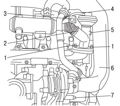
Pic. 4.82. EGR valve (EGR): 1 - nuts, 10 Nm; 2 - clamp; 3 - bolt, 10 Nm; 4 - tube; 5 - valve of the exhaust gas recirculation system; 6 - charge air supply pipeline; 7 - bolt, 10 Nm
Turn out bolts 3 and 7 (pic. 4.82).
Take the pipe 6 supply of charge air to the right.
Disconnect the tube 4.
Loosen and remove clamp 2.
Loosen nuts 1.
Remove valve 5 of the exhaust gas recirculation system.
Installation
Attention! When installing the exhaust gas recirculation valve, you must use a new clamp 2 (see fig. 4.82), clamps of fastening of system of release of the fulfilled gases and sealing of the valve.
Installation is carried out in the reverse order of removal, taking into account the following.
Clear a carving of bolts of fastening of a branch pipe on an entrance to a turbocharger.
Clean bolts 3 and 7.
Tighten nuts 1 to 10 Nm.
Coat the threads of bolts 3 and 7 with LOCTITE FRENETANCH to prevent self-loosening, screw in and tighten the bolts to 10 Nm.
Tighten the engine mount bolts to 60 Nm.
Tighten the stabilizer bar mounting bolts on the side of the sub-frame to 40 Nm.
Tighten the stabilizer bar mounting bolts on the engine side to 55 Nm.