



Table of contents: Removal 🠇 Installation 🠇
Removal
Caution! Do not disconnect the injector connectors while the engine is running.
Turn off the ignition and disconnect the cable from the negative battery terminal.
Before starting any work on the fuel system, wait 30 seconds after the engine has stopped.
Remove the decorative cover from the engine.
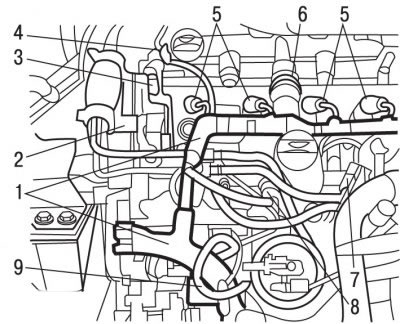
Figure 4.69. Location of wires and contact connectors on the DW10TD engine: 1 - wiring harness; 2 - support for the pump for filling the system with fuel; 3 - support for the decorative engine cover; 4, 7, 8 - sensors; 5-pin connectors; 6 - oil vapor recovery tube; 9 - fuel supply pipe
Disconnect the contact connectors from sensors 4, 7, 8 (figure 4.69).
Disconnect the 5-pin connectors from the injectors.
Move aside the wiring harness of 1 injectors.
Move aside the oil vapor recovery tube 6 and the pump for filling the system with fuel.
Remove support 2 of the fuel filling pump.
Remove support 3 of the decorative engine cover.
Use a screwdriver to push the latch up and remove the diesel fuel return pipe.
Use SODIMAC 35 to clean the high-pressure fuel pipe union nuts and the areas around the nuts.
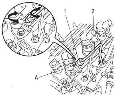
Figure 4.70. High pressure fuel line: 1 - connecting nut, 25 Nm; 2 - high pressure fuel pipe; 3 - connecting nut, 28 Nm; A - hexagon on the nozzle
Holding the hexagons A with a wrench (figure 4.70) on the injectors, use the second key to unscrew the connecting nuts 1 securing the high-pressure fuel pipes to the injectors.
Loosen the connecting nuts 3 securing the high-pressure fuel pipes to the fuel distributor and remove the fuel pipes 2. To prevent dirt from getting in, close the fuel pipes and fittings on the fuel distributor with suitable plugs.
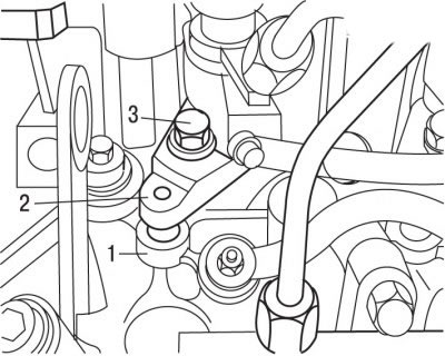
Figure 4.71. Injector mounting elements: 1 - thrust pin of the injector mounting bracket; 2 - bracket; 3 - bolt
Remove bolts 3 (figure 4.71), remove the 2 injector mounting brackets and the 1 injector mounting bracket thrust pins.
Caution! When re-grinding the mating surface of the cylinder head, the thrust pins of the injector mounting brackets must be replaced with corresponding pins of repair dimensions.
Carefully remove the injectors from the cylinder head.
Remove the sealing bushings (between the injector and the cylinder head).
Close the injector sockets and injector nozzles with suitable plugs.
Installation
Caution! When installing injectors, it is necessary to use new high-pressure fuel lines and sealing bushings.
Remove the plugs covering the injector sockets.
Install new sealing bushings on the injectors.
Install the injectors on the cylinder head.
Install the injector mounting bracket thrust pins, brackets and secure them with bolts, tightening them by hand at this stage.
Connect the diesel fuel return pipes to the injectors.
Install the high-pressure fuel lines onto the injectors and fuel distributor and secure them with the union nuts, tightening them by hand at this stage.
Tighten the injector bracket mounting bolts to 35 Nm.
Pre-tighten the connecting nut mounting bolts to 24 Nm.
Tighten the union nuts 3 (see Figure 4.70) torque of 28 Nm.
Tighten the connecting nuts 1 to 25 Nm.
Further installation is carried out in the reverse order of removal.
Conduct computer programming.
Start the engine.
Check for fuel leaks.