



Table of contents: Removal 🠇 Installation 🠇
Removal
Turn off the ignition and disconnect the cable from the negative battery terminal.
Before starting any work on the fuel system, wait 30 seconds after the engine has stopped.
Remove the decorative cover from the engine.
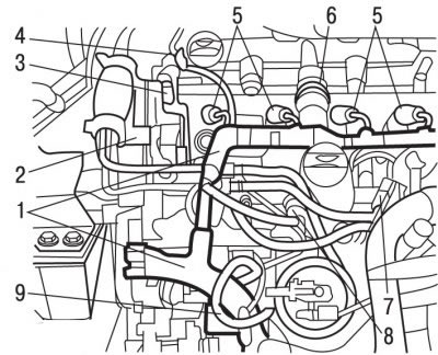
Figure 4.69. Location of wires and contact connectors on the DW10TD engine: 1 - wiring harness; 2 - support for the pump for filling the system with fuel; 3 - support for the decorative engine cover; 4, 7, 8 - sensors; 5-pin connectors; 6 - oil vapor recovery tube; 9 - fuel supply pipe
Disconnect the contact connectors from sensors 4, 7, 8 (see figure 4.69).
Disconnect the 5-pin connectors from the injectors.
Move aside the wiring harness of 1 injectors.
Move aside the oil vapor recovery tube 6 and the pump for filling the system with fuel.
Remove support 2 of the fuel filling pump.
Remove support 3 of the decorative engine cover.
Remove fuel supply pipe 9.
Disconnect the diesel fuel pressure return line from the fuel pump.
Use SODIMAC 35 to clean the high-pressure fuel line connecting nuts and the area around the nuts.
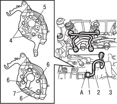
Figure 4.76. High pressure fuel pump mounting: 1 - connecting nut, 25 Nm; 2 - high pressure fuel pipe; 3 - connecting nut, 28 Nm; 4 - bolts; 5 - nut; 6 - bolts; 7 - rear support of the high-pressure fuel pump
Holding the Allen key A with a wrench (figure 4.76) on the high-pressure fuel pump, use the second wrench to unscrew the connecting nut 1 securing the high-pressure fuel line 2.
Unscrew the connecting nut 3 securing the high-pressure fuel line 2 to the fuel distributor and remove the fuel line.
Unscrew bolts 6 and remove them together with washers.
Remove the rear support 7 of the high pressure fuel pump.
Install crossmember 0102-D to support the engine. Hook the crossmember hook onto the right engine lifting eye.
Remove the right engine mount.
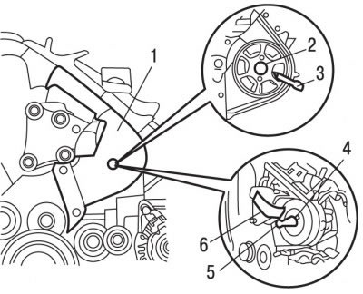
Figure 4.77. Fastening the high-pressure fuel pump pulley: 1 - upper front toothed belt cover; 2 - nut; 3 - special pin 0188-V; 4 - additional hub 0188-AB; 5 - bolt; 6 - special device for fastening the high-pressure fuel pump pulley
Remove the upper front cover 1 (figure 4.77) toothed belt.
Using special pin 0188-V, secure the fuel pump pulley from turning and unscrew nut 2 that secures the pulley.
Install special tool 6 and additional hub 0188-AB 4 to secure the high pressure fuel pump pulley. Tighten the special tool 6 mounting bolts to 40 Nm and the additional hub 4 bolts to 15 Nm.
Unscrew bolts 4 and nut 5 (see Figure 4.76) fuel pump mounts.
Screw in bolt 5 (see Figure 4.77) fuel pump pulley mounts and remove the high pressure fuel pump.
Installation
Remove additional hub 0188-AB 4 (see Figure 4.77) high pressure fuel pump pulley mounts.
Install the high pressure fuel pump.
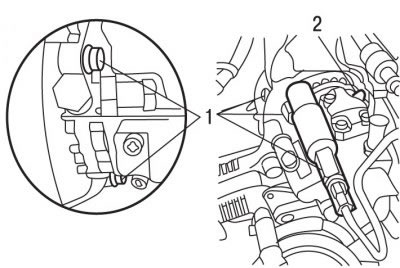
Figure 4.78. Location of bolts (1) and nuts (2) for fastening the high-pressure fuel pump
Source of the article is website: PEUGEOTBOOK
Screw in and tighten bolts 1 and nuts 2 (figure 4.78) fuel pump mounting torque 23 Nm.
Screw in and tighten nut 2 by hand (see Figure 4.77) high pressure fuel pump pulley mounts.
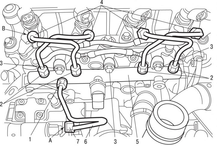
Figure 4.68. Fuel distributor (Common Rail): 1, 2 - connecting nuts, 28 Nm; 3 - bolts, 23 Nm; 4, 7 - connecting nuts, 25 Nm; 5 - fuel distributor; 6 - high pressure tube; A - hexagon on the high pressure fuel outlet fitting; B - hexagon on the nozzle
Install high pressure pipe 6 and secure it with union nuts 1 and 7 (see figure 4.68), tightening them by hand at this stage.
Pre-tighten the connecting nut mounting bolts to 24 Nm.
Tighten the union nut 1 securing the high-pressure pipe to the fuel distribution line to a torque of 28 N·m.
Tighten the connecting nuts 7 securing the high-pressure pipe to the fuel pump to 25 N·m.
Further installation is carried out in the reverse order of removal.
Tighten bolts 6 (see Figure 4.76) fastening the rear support of the fuel pump with a torque of 23 Nm.
Tighten nut 2 (see Figure 4.77) fastening the high pressure fuel pump pulley with a torque of 50 Nm.
Tighten the high pressure fuel pump mounting stud to the support to a torque of 65 N·m.
Tighten the engine mount mounting bolt to 60 Nm.
Fill the circuit with fuel using a hand priming pump.
Conduct computer programming.
Start the engine.
Check for fuel leaks.