
Removing
Disconnect the wire from the negative battery terminal.
Remove the right front wheel.
Remove the right front wheel arch mudguard.
Remove the accessory drive belt.
Remove the decorative casing from the engine.
DW10ATED engine
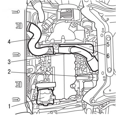
Pic. 4.43. Location of the compressor in the engine compartment with the DW10ATED engine: 1 - air conditioner compressor; 2 - jet bracket; 3 - air pipe at the outlet of the turbocharger; 4 - air cooler; 5 - bump stop of the shock-proof amplifier 6 - sub-frame
Unscrew the nut, remove the bolt and remove the reaction arm 2 (see fig. 4.43) engine mounts.
Remove the air pipe 4 to the air cooler.
Remove the air pipe 3 at the outlet of the turbocharger.
All engines
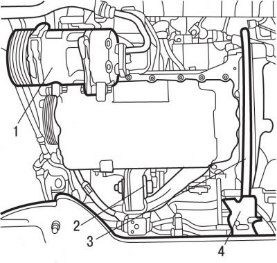
Pic. 4.42. Location of the air conditioning compressor in the engine compartment of the DW10TD engine: 1 - air conditioner compressor; 2 - jet bracket; 3 - shockproof amplifier of the sub-frame; 4 - chipper
Remove fender 5 (see fig. 4.43), 4 (see fig. 4.42).
Insert special tool 0188-F, which fixes the flywheel from turning.
Turn out a bolt of fastening of a pulley of a belt of a drive of auxiliary units and screw a bolt without a washer into place.
Remove the special tool 0188-F, which fixes the flywheel from turning.
Using pulley puller 0188-P, remove the accessory drive belt pulley.
Disconnect the turbocharger exhaust pipe.
DW10ATED engine
Disconnect the fuel supply and return pipes from the engine. Close the ends of the tubes with suitable plugs.
Disconnect the particulate filter from the pre-catalytic converter.
All engines
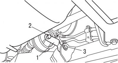
Pic. 4.49. Engine Reaction Arm Mount: 1 - jet lever; 2 - bolt, 55 Nm; 3 - bolt, 40 Nm
Turn out bolts and remove a jet arm 1 (see fig. 4.49) engine mounts.
Remove the air intake duct.
Disconnect and move aside the hand pump to bleed the fuel system.
Install cross member 0911-AY to support the engine.
Protect the inside of the cooling system heatsink with a piece of cardboard cut to fit the heatsink.
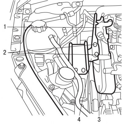
Pic. 4.57. Engine Mount: 1 - hand pump support for pumping the fuel system; 2 - bolts; 3 - toothed belt casing; 4 - right engine support bracket
Remove support 1 (pic. 4.57) manual pump for pumping the fuel system.
Remove the toothed belt covers.
Remove bolts 2 and remove the right engine mount bracket.
Turn the crankshaft of the engine to a position in which the piston of the 1st cylinder is set to the TDC position.
Use special tool 0188-Y to secure the crankshaft from turning.
Fix the camshaft pulley with special tool 0188-M.
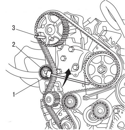
Pic. 4.58. Fixing the camshaft pulley with a special tool 0188-M (3) and the direction of the key (1) for loosening the nut of the tension roller (2)
Loosen nut 2 (pic. 4.58) fastening the tension roller and re-tighten it after the maximum loosening of the tension of the toothed belt.
Remove the toothed belt.
Installation
Attention! Do not twist or bend the toothed belt. Do not expose the toothed belt to oil, coolant or fuel. If the outer surface of the toothed belt is significantly worn or split, check the condition of the idler and idler roller raceways. If there are any defects on the toothed belt, replace it.
Check that the water pump, idler and idler rollers rotate smoothly and evenly.
If the guide roller was replaced, tighten the roller mounting bolt to 43 Nm.
Pic. 4.59. Location of pulleys and rollers: 1 - guide roller; 2 - water pump pulley; 3 - tension roller; 4 - camshaft pulley; 5 - bolts
Remove bolts 5 (pic. 4.59) mounting pulley 4 camshaft.
Check that the toothed belt pulley turns freely on the camshaft.
Tighten by hand the bolts 5 fastening the pulley 4 of the camshaft.
Turn the pulley fully clockwise.
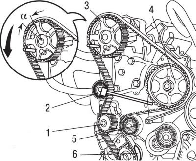
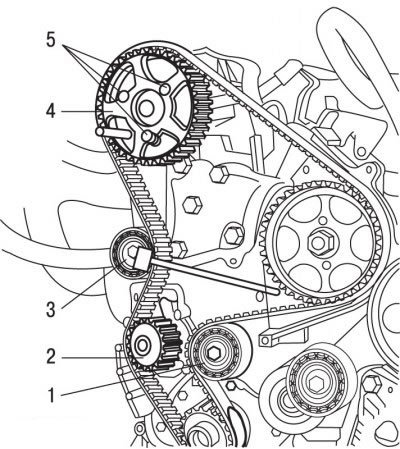
Pic. 4.60. The location of the toothed belt on the pulleys: 1 - water pump; 2 - tension roller; 3 - camshaft pulley; 4 - high pressure fuel pump; 5 - guide roller; 6 - fixture 0188-K for maintaining the belt on the crankshaft pulley; a - angular displacement of the pulley
Install the toothed belt on the crankshaft pulley and secure it with the special tool 6 (pic. 4.60) 0188-K for belt support.
Install while pulling the toothed belt over the pulleys in the following order:
- guide roller 5;
- pulley 4 of the high pressure fuel pump;
- camshaft pulley 3;
- tension roller 2;
- pulley 1 water pump.
Install the previously removed belt in accordance with the marked marks.
When installing the toothed belt onto the camshaft pulley, first rotate the pulley against normal engine rotation to facilitate belt installation.
Attention! Angular movement a (see fig. 4.60) pulley relative to the belt should not exceed the width of one tooth.
Bring the tension roller to the toothed belt and tighten the roller fastening bolt to 1 Nm.
Remove tool 6-0188-K holding the timing belt on the crankshaft pulley.
Toothed belt pretension
Install the sensor of the device 0192 on the branch of the toothed belt between the pulleys of the fuel pump and the camshaft to measure the belt tension. Check that the sensor does not touch surrounding machinery.
Using lever 0188-J2, turn the tension roller counterclockwise until the belt tension is (98±2) units. In this position, tighten the tension roller mounting bolt to 23 Nm.
Remove the 0192 gauge for measuring belt tension.
Tighten the camshaft pulley bolts.
Remove tools 0188-Y and 0188-M fixing the camshaft and crankshaft.
Rotate the engine crankshaft 10 revolutions.
Final tension of toothed belt
Fix the crankshaft and camshaft pulley with special tools 0188-Y and 0188-M.
Remove bolts 5 (see fig. 4.59) fastening the camshaft pulley.
Tighten by hand the bolts 5 fastening the pulley 4 of the camshaft.
Turn out bolts 5 fastenings of a pulley of a camshaft on 1/6 turns.
Loosen the idler pulley bolt.
Install the sensor of the device 0192 on the branch of the toothed belt between the pulleys of the fuel pump and the camshaft to measure the belt tension.
Using lever 0188-J2, turn the tension roller counterclockwise until the belt tension is (54±2) units. In this position, tighten the tension roller mounting bolt to 23 Nm.
Tighten the camshaft pulley bolts.
Remove the 0192 gauge for measuring belt tension.
Reinstall the 0192 belt tension gauge.
The tension value of the toothed belt should be in the range of 51-57 units.
Attention! If the belt tension obtained is out of tolerance, loosen the belt and repeat the belt tensioning operations.
Remove the 0192 gauge for measuring belt tension.
Remove tools 0188-Y and 0188-M fixing the camshaft and crankshaft.
Checking toothed belt tension adjustment
Rotate the engine crankshaft 10 revolutions.
Install special tool 0188-Y to fix the crankshaft.
Visually check that the difference between the hole in the camshaft flange and the hole for the corresponding retainer is no more than 1 mm.
Remove tool 0188-Y fixing the crankshaft.
Install the toothed belt guards.
Install the engine mount pad.
Tighten the camshaft timing belt pulley bolts to 61 Nm.
Install the hand pump support to bleed the fuel system.
Install special tool 0188-F, which fixes the flywheel from turning.
Reinstall reaction bracket 1 (see fig. 4.49) engine mounts and tighten the bracket mounting bolts: bolt 2 - torque 55 Nm; bolt 3 - torque 40 Nm.
Install the accessory drive belt pulley.
Using an M16x150 tap in the crankshaft, clean the thread for the central pulley mounting bolt.
Coat the threads of the crankshaft pulley center bolt with LOCTITE FRENETANCH to prevent self-loosening (blocking fluid), screw in the bolt and tighten it to a torque of 40 Nm, then tighten it by an angle of 51°.
Install the accessory drive belt.
Remove the special tool 0188-F, which fixes the flywheel from turning.
Further installation is carried out in the reverse order of removal.
Install the front wheels and secure with bolts, tightening them to a torque of 90 Nm.
Program the engine control computer.