
Removing
Attention! All clamps and clamps that will be damaged or cut during removal must be replaced with new ones when installing the head of the block. When replacing the block head, fill the cooling system with fresh coolant.
Switch off ignition and disconnect a wire from the negative plug of the storage battery.
Drain the coolant.
Remove the front wheels.
Remove the front mudguards.
Remove the decorative casing and cover from the right side of the engine compartment from the engine.
Remove the air filter.
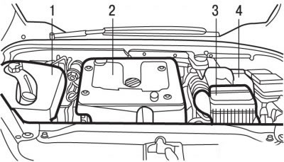
Pic. 4.44. Location of parts and assemblies in the engine compartment with the DW10TD engine: 1, 2 - decorative covers; 3 - air filter; 4 - battery
Remove battery 4 (see fig. 4.44) and its bracket. Access to one of the bracket mounting bolts is possible through the left wheel arch.
Remove the front shield cross member.
Remove the soundproof mats from the bulkhead of the engine compartment.
Remove and set aside and secure the brake fluid reservoir.
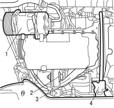
Pic. 4.42. Location of the air conditioning compressor in the engine compartment of the DW10TD engine: 1 - air conditioner compressor; 2 - jet bracket; 3 - shockproof amplifier of the sub-frame; 4 - chipper
Unscrew the nut, remove the bolt and remove the reaction arm 2 (see fig. 4.42) engine mounts
Remove the shockproof reinforcement of the underframe 3.
Remove system of release of the fulfilled gases.
Attention! The connecting element in the front exhaust pipe must be protected from any mechanical damage. The connector in the front exhaust pipe must not be bent more than 20°or misaligned by 20 mm axially and 25 mm radially, otherwise it will be damaged.
Remove the accessory drive belt.
Remove the toothed belt.
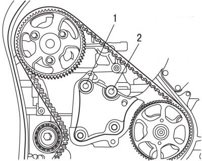
Pic. 4.50. Bracket bolt locations: 1 - bolt, 20 Nm; 2 - bolt, 45 Nm
Remove bolts 1 and 2 (pic. 4.50) bracket mounting.
Install right engine mount bracket and secure with bolts finger-tight.
Remove the 0911-AY engine support cross member that was installed when the toothed belt was removed.
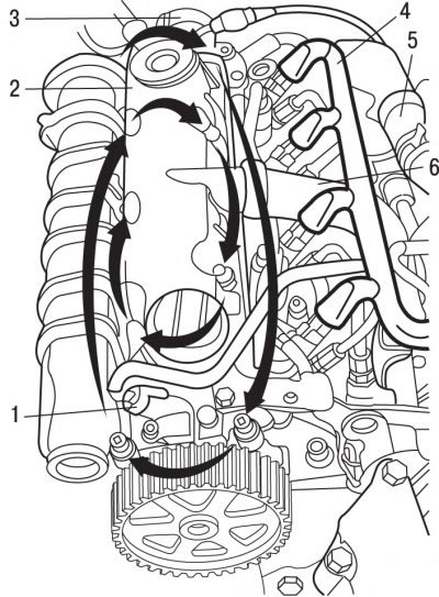
Pic. 4.51. The sequence of reversing the bolts of the cylinder head cover: 1 - pin connector; 2 - cylinder head cover; 3 - rubber «pear» to fill the system with fuel; 4 - harness of electrical wires; 5 - branch pipe of the cooling system; 6 - hose for returning condensed oil vapors to the unit
Disconnect pin 1 (pic. 4.51).
Disconnect from the engine a harness 4, a branch pipe of the cooling system 5, a hose of the vacuum brake booster and a rubber «pear» to fill the system with fuel 3.
Disconnect the electrical connectors from the glow plugs of the preheating system.
Disconnect from the cylinder head and take aside the hose for returning condensed oil vapors to the cylinder block 6, wiring harnesses, tubes and hoses of the heater radiator.
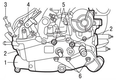
Pic. 4.52. Mounting block for coolant outlet: 1 - block for the exit of the coolant; 2 - nuts, 20 Nm; 3 - pointer tube (probe) oil level; 4 - support; 5 - studs, 25 Nm; 6 - bolts, 20 Nm
Remove support 4 (pic. 4.52).
Turn out a bolt and remove a tube 3 pointers (probe) oil level.
Turn out bolts 6 of fastening of the block for an exit of a cooling liquid.
Turn out nuts 2 and hairpins.
On DW10ATED engines, remove the current cylinder phase sensor.
In a spiral, starting from the outside, remove the bolts and remove the cylinder head cover.
Move the coolant outlet block away from the cylinder head.
Turn out a bolt of fastening of a tube of the oil filter.
Use SODIMAC 35 to clean the union nuts of the high pressure fuel pipes and the area around the nuts.
Loosen the connecting nuts of the high pressure fuel pipe connecting the high pressure fuel pump and the fuel distributor (Common Rail) and remove the fuel pipe.
Remove glow plugs.
Turn out bolts and remove brackets of fastening of atomizers.
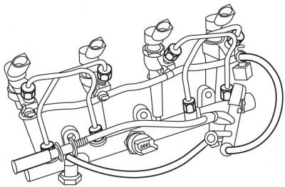
Pic. 4.53. Injectors, high pressure pipes and fuel distributor assembly
Carefully remove the injectors from the cylinder head and at the same time remove the high pressure pipes and fuel rail assembly (pic. 4.53).
Remove the steering gear heat shield.
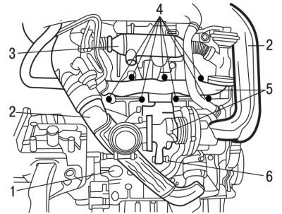
Pic. 4.54. Location of engine elements: 1 - oil return pipe; 2 - air supply pipe to the turbocharger; 3 - node of the exhaust gas recirculation system; 4 - hooks for fastening the turbocharger and exhaust manifold; 5 - exhaust manifold; 6 - bracket for the lower mounting of the turbocharger
Remove pipes 2 (pic. 4.54) air supply to the turbocharger.
Disconnect the oil return pipe 1 from the cylinder block.
Remove node 3 of the exhaust gas recirculation system.
Remove bracket 6 of the lower mounting of the turbocharger.
Turn out nuts 4 fastenings of a final collector.
Remove and set aside the exhaust manifold 5 together with the turbocharger.
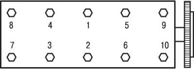
Pic. 4.55. The sequence of tightening the cylinder head bolts on the DW10TD engine
In the reverse order to tightening, gradually loosen and then completely unscrew the cylinder head bolts (pic. 4.55).
Install curved levers in the holes of the cylinder head and, by pressing them, separate the head from the cylinder block.
Remove the cylinder head and place it on a soft base.
Preparing the head for installation
The mating surfaces of the head and cylinder block must be perfectly clean. Use a hard plastic or wooden scraper to clean them. Be careful when cleaning as aluminum alloy is very easy to damage. Make sure that carbon deposits do not get into the channels of the lubrication and cooling system. This is especially important for the lubrication system, as deposits can block the oil supply to engine parts. Clean channels if necessary.
Check the mating surfaces of the head and cylinder block: they should not have nicks, deep scratches or other damage. Small defects can be eliminated by machining. In case of significant defects, the parts must be replaced.
Using a metal ruler and feeler gauge, check the flatness of the mating surfaces.
If the flatness deviation exceeds 0.05 mm, the head must be reground.
Clean the threads of the cylinder head bolt holes.
Clean the bolt holes in the block. Screwing a bolt into an oil-filled hole can rupture the block due to hydraulic pressure.
Before reusing the bolts, measure the length of the bolts to the base of the head, which should be 133.4mm for the DW10TD engine and 134mm for the DW10ATED engine.
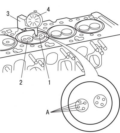
Pic. 4.7. Valve protrusion measurement: 1 - exhaust valve; 2 - inlet valve; 3 - stand; 4 - dial indicator; A - measurement points
Check the protrusion of the valves in relation to the plane of the cylinder head at points A (see fig. 4.7), which should be 0.2 mm. The protrusion value must be calculated as an average based on four measurements.
Remove the device that fixes the crankshaft from turning.
Measure the protrusion of the pistons from the cylinder block and, according to this value, select the thickness of the new cylinder head gasket.
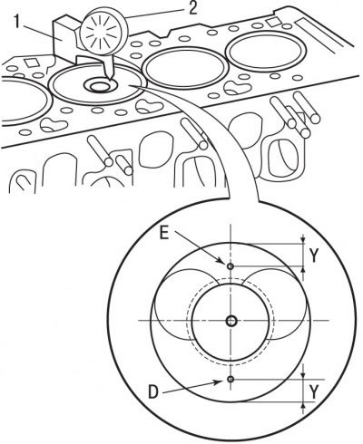
Pic. 4.8. Measurement of piston protrusion from the cylinder block: 1 - stand; 2 - dial indicator; D, E - measurement points; Y = 10.0 mm
Mount the dial indicator on the stand on the cylinder block (see fig. 4.8).
Install the indicator tip on the top plane of the cylinder block and set the indicator to 0.
Install the measuring tip of the indicator on one of the control points.
Turn the crankshaft until one of the pistons reaches TDC, but do not go over it. Read the piston protrusion value on the indicator.
The protrusion value must be calculated as an average based on measurements at two points.
Measure the protrusion of the other pistons in the same way.
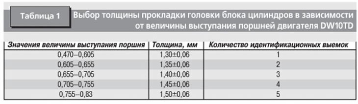
The largest average piston protrusion determines the thickness of the cylinder head gasket (tab. 1).
Installation
Turn the crankshaft of the engine to a position in which the piston of the 1st cylinder is set to the TDC position.
Use special tool 0188-Y to secure the flywheel against turning.
Check for the presence of dowel sleeves in the cylinder block.
A new cylinder head gasket must be removed from the packaging immediately before installation.
Install a new cylinder head gasket having a predetermined thickness.
Check that the camshaft is secured against turning with a special tool.
Install the cylinder head.
Apply a thin layer of G10 grease to the threads of the cylinder head bolts, insert the bolts and tighten them by hand.
In the sequence shown in fig. 4.55, tighten the cylinder head bolts:
- 1st stage - tighten with a torque of 20 Nm;
- 2nd stage - tighten with a torque of 60 Nm;
- 3rd stage - tighten by an angle of 220.
Note. After warming up the engine, additional tightening of the cylinder head bolts is not required.
Install the injectors, high pressure pipes and fuel rail assembly.
Screw in glow plugs.
Install the cylinder head cover with a new gasket.
Insert and in the reverse order of turning out, tighten the cylinder head cover bolts to a torque of 10 Nm (see fig. 4.51).
Slide the bottom of the engine forward, install the exhaust manifold with turbocharger and secure with bolts.
Install the turbocharger mounting bracket.
Install the EGR assembly.
Connect a tube of a radiator of an air conditioning system.
Set block 1 (see fig. 4.52) for the coolant outlet with a new gasket.
Apply LOCTITE FREIN FILET to the stud threads to prevent self-loosening (blocking fluid), screw in and tighten to 25 Nm.
Screw nuts 2 onto the studs and tighten them to a torque of 20 Nm.
Screw in the bolts 6 for fastening the block for the outlet of the coolant and tighten them to a torque of 20 Nm.
Install the cross member 0911-AY to support the engine and tighten the attachment arms so that the weight of the engine is supported by the attachment.
Remove the right engine mount.
Apply to bolt thread 2 (see fig. 4.50) block fixings LOCTITE FREIN FILET locking compound preventing its self-unscrewing (blocking fluid), screw in and tighten to 45 Nm. Tighten bolt 1 to 20 Nm.
Install support 4 and tube 3 (see fig. 4.52) pointer (probe) oil level.
Install the toothed belt.
On DW10ATED engines, adjust the position of the current cylinder phase sensor.
Install the accessory drive belt.
Further installation is carried out in the reverse order of removal, taking into account the following.
Fill with coolant and bleed air from it.
Connect the wire to the negative battery terminal.
Program the engine control computer.
Start the engine.
Check the tightness of the connections.
Increase the engine speed to 3500 min-1.
Check the tightness of the connections.