



Table of contents: Removal 🠇 Installation 🠇
Removal
Caution! Use chalk, marker, or paint to mark the direction of rotation of the accessory drive belt. If the drive belt for the attachments rotates in the opposite direction during installation, this will lead to its destruction.
Remove the front right wheel.
Remove the protective cover under the engine.
Remove the front right mudguard.
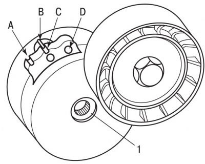
Figure 4.56. Dynamic tensioner: 1 - bolt, 45 Nm; A - mark of maximum belt stretch; B - mark for checking belt tension (applied to the engine); C - zero stretch mark; D - hole for installing a pin with a diameter of 4 mm
Using the special lever 0188-Z, compress the dynamic tensioner spring, which will reduce the belt tension (figure 4.56).
Using special tool 0188-Q1, fix the dynamic tensioner in this position. Instead of the 0188-Q1 fixture, a 4 mm diameter pin can be used.
Remove the accessory drive belt from the pulleys.
Check that the dynamic tensioner guide roller and tension roller rotate evenly and smoothly.
Installation
The marking system on the dynamic tensioner allows monitoring of the accessory drive belt stretch. When marks A and B are aligned, it is time to replace the belt.
Place the belt over the crankshaft and accessory pulleys and finally over the idler pulley.
Make sure the belt is properly positioned on all pulleys and roller.
Using special lever 0188-Z, compress the dynamic tensioner spring and remove special tool 0188-Q1 or 4 mm diameter pin and remove the lever, while the dynamic tensioner tension roller will tension the accessory drive belt.
Further installation is carried out in the reverse order of removal.