
Turn out bolts and separate a transmission from the engine.
On the left rear side of the engine, loosen the cooling system pipe clamp and remove the pipe.
Remove the air distributor together with the throttle body and fuel injection rail.
Remove the oil filter, oil filter support, seal and oil level indicator tube.
Mark with a marker or paint the position of the clutch assembly in relation to the flywheel.
Gradually slacken the torques of the clutch assembly mounting bolts diagonally by turning each bolt half a turn until the spring action stops and the bolts can be unscrewed by hand.
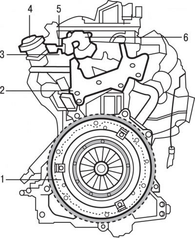
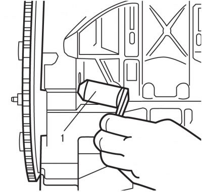
Pic. 3.55. Components that must be removed first when disassembling the EW10J4 engine: 1 - clutch pressure plate; 2 - plate on the coolant outlet block; 3 - high pressure fuel line; 4 - valve; 5 - fuel return pipe; 6 - high pressure fuel pump
Remove pressure plate 1 (pic. 3.55), while supporting the driven disc so that it does not fall out.
Clean the clutch release bearing from dirt, but do not use solvents.
Remove plate 2 on the coolant outlet block.
Remove damper and valve 4.
Remove fuel return pipe 5 and high pressure fuel line 3.
Remove the high pressure fuel pump 6.
To prevent the ingress of dirt, close the pipes and fuel supply holes with appropriate plugs
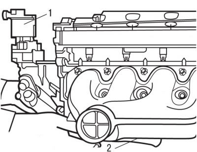
Pic. 3.56. Location of coolant outlet block (1) and connecting pipe (2) outlet block/water pump
Remove Block 1 (pic. 3.56) coolant outlet and connecting pipe 2 of the outlet / water pump unit.
Remove the coolant outlet block gasket.
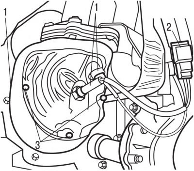
Pic. 3.57. Location of oxygen sensors (1), pin connector (2) and bolts (3)
Unclip connector 2 (pic. 3.57).
Remove the oxygen sensors 1.
Remove three screws 3.
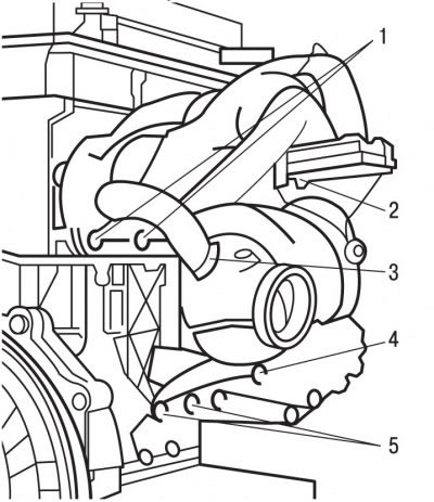
Pic. 3.58. Exhaust manifold fasteners: 1, 2, 5 - nuts; 3 - clamp; 4 - nut
Loosen clamp 3 (pic. 3.58), unscrew nut 4, nuts 2, nuts 1 and remove the exhaust manifold.
Pic. 3.59. Installation of a special device for fixing the flywheel from turning
Turning the flywheel, align the blind hole on the flywheel with the hole in the cylinder block and special tool 1 (pic. 3.59) block the flywheel from turning.
Turn out bolts of fastening of covers of heads of the block of cylinders.
Remove the current phase sensor in the cylinder.
Remove the cylinder head covers.
Turn out three bolts and remove the block of coils of ignition.
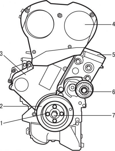
Pic. 3.60. Location of engine parts: 1 - pulley mounting bolt; 2 - auxiliary drive belt pulley; 3 - lower casing of the toothed belt; 4 - the upper casing of the toothed belt; 5 - engine mount pillows; 6 - tension roller; 7 - central bolt for fastening the toothed belt pulley to the crankshaft
Remove four screws 1 (pic. 3.60) attaching the accessory drive belt pulley and remove the pulley 2.
Turn out a bolt and remove a tension roller 6.
Turn out bolts and remove a pillow of a suspension bracket of the engine 5.
Remove top 4 and bottom 3 toothed belt casings.
Loosen the central bolt 7 securing the toothed belt pulley to the crankshaft.
Remove the flywheel locking tool.
Use the special tool 1 to secure the engine crankshaft from turning.
Secure the camshafts against rotation with special tools.
To loosen the tension of the toothed belt, loosen the tensioner roller mounting bolt and turn the tensioner roller clockwise.
Remove the toothed belt from the pulleys.
Completely turn out a bolt of fastening and remove a tension roller.
Turn out a bolt of fastening of a directing roller and remove it.
Turn out the central bolt of fastening of a pulley of a gear belt to a cranked shaft, remove a flange and a pulley of a gear belt.
Turn out bolts and remove the water pump.
Holding the wrench by the flat of the exhaust camshaft from turning, unscrew the mounting bolt and remove the toothed belt pulley from the camshaft.
Remove the timing belt pulley from the intake camshaft in the same manner.
Remove the rear toothed belt cover.
Special tool 1 (see fig. 3.59) block the flywheel from turning.
Remove the eight bolts and, being careful, remove the flywheel.
Remove the flywheel locking tool.
Turn the engine with the oil pan up.
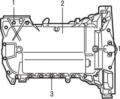
Pic. 3.61. Bolt location (1 and 3) oil pan mountings (2)
Remove 19 bolts 3 (pic. 3.61) oil pan mountings 2.
Turn out seven bolts 1 fastenings of the back and forward left parts of the oil pallet.
Remove the oil pan.
Use a plastic or wooden scraper to clean the mating surfaces of the engine and oil pan from the old gasket.
Turn out bolts and remove the plate interfering with an emulsification of oil.
Turn out bolts and remove an oil pickup with the mesh filter.
Turn out bolts and remove a forward cover with the oil pump. Remove the crankshaft seal from the cover.
In the reverse order to tightening, gradually loosen and then completely unscrew the cylinder head bolts.
Remove the cylinder head and place it on a soft base.
Remove the cylinder head gasket.
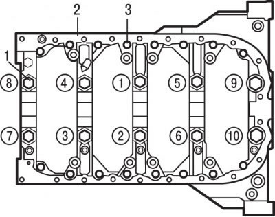
Pic. 3.62. Location and tightening sequence (numbers in circles) bolts M11 (1) and M6 bolts (3) fastenings of the crankcase of the main bearing caps (2)
Remove 16 bolts 3 (pic. 3.62), located around the perimeter of the crankcase main bearing caps.
In the reverse order of tightening, gradually loosen and then completely unscrew the bolts 1 securing the crankcase of the main bearing caps 2.
Remove the main bearing cap housing. If necessary, use a hammer to separate the main bearing cap housing from the cylinder block.
Turn the crankshaft and set the piston of the 1st cylinder to the bottom dead center position (NMT).
If a shoulder has formed in the upper part of the cylinder, then it must be removed with a reamer or scraper without damaging the cylinder wall. The formation of a shoulder indicates increased wear on the cylinder.
Turn out bolts of fastening of a rod cover of the first cylinder. Remove the cover and remove the lower connecting rod bearing. If the insert is to be installed again, stick it with adhesive tape to the removed cover.
Use a hammer handle to push the piston into the cylinder and remove it through the top of the cylinder block. Remove the upper connecting rod bearing and tape it to the removed connecting rod.
Place the cover on the connecting rod and secure with bolts to maintain the previous order of assembly of the parts.
After repeating the above operations, remove the connecting rods with pistons in the remaining cylinders.
Before checking pistons with connecting rods, remove the piston rings from the pistons and thoroughly clean the pistons.
Remove the crankshaft, main bearings and thrust washers.
To remove the piston rings from the pistons, open the ring and insert two or three old feeler blades evenly around the circumference under it and slide the ring off the piston along them. Be careful not to scratch the piston with the ends of the ring. Rings are very brittle and can crack if unclenched too much. Handle the sharp working edges of the piston rings with care to avoid cuts. Keep each set of rings with the pistons to reinstall them.
Clean all carbon deposits from the top of the piston.
Remove carbon deposits from the piston ring grooves using the old piston ring.
If necessary, press the piston pin out of the piston and connecting rod.
Attention! The piston from which the piston pin has been pressed out cannot be reused.