



Recommendations for engine removal
Please read this section carefully before you begin.
If the engine is removed for repair, it is necessary to select a location for the work, provide space for servicing and storing spare parts. It is recommended that repairs be carried out at a service station or in a garage with a level, horizontal floor covered with a clean, hard surface.
Before removal, clean and wash the engine and engine compartment. To remove, use a lifting mechanism that allows you to safely lift the power unit.
If you are removing the power unit for the first time, you should invite an experienced specialist. Some jobs should be done with an assistant.
All clamps and clips that are damaged or cut during engine removal are replaced with new ones during engine assembly.
Depending on the year of manufacture and the vehicle's configuration, electrical wires, pipes, and hoses may be located differently in the engine compartment. Therefore, before disconnecting electrical connectors and disconnecting pipes or hoses, it is recommended to mark them with adhesive tape.
The engine is removed forward together with the gearbox.
The drained coolant must be collected and disposed of.
Removal
Place the vehicle on a two-post lift.
Open the hood to the service position and secure it with the bolt and nut system.
Remove the decorative cover from the engine.
Relieve the pressure in the fuel system by connecting special tool 0141-T1 to the SHRADER valve and collecting the fuel in a container.
Drain the coolant.
Drain the oil from the gearbox.
Remove the accessory drive belt.
Remove the front wheels.
Remove the front bumper, headlights and bumper reinforcement beam.
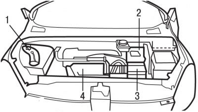
Figure 3.51. Location of parts and assemblies in the engine compartment with the EW10J4 engine: 1 - upper right decorative cover; 2 - battery cover; 3 - air filter; 4 - resonator
Remove the upper right decorative cover 1 (figure 3.51).
Remove air filter 3, resonator 4, throttle body cover and air intake.
Remove the flexible clutch cable.
Disconnect the hose from the brake booster.
Disconnect the fuel supply and return lines, as well as the fuel vapor suction line fittings.
Remove the battery cover 2.
Remove the left front wheel arch mudguard.
From under the left front wheel arch, unscrew the battery support mounting bolt.
Remove the battery.
Remove the battery support.
Disconnect the constant velocity joints and shock absorbing elements attached to the lower gearbox housing from the gearbox.
Using special tools, disconnect the gearbox control rods.
Disconnect the exhaust pipe from the exhaust manifold.
Remove the clutch drive mechanism.
Remove the engine mount torque bracket.
Caution! Do not open the air conditioning system cooling circuit.
Move aside and secure the air conditioning condenser.
Remove the air conditioning compressor mounting bolts and move it to the side without disconnecting the pipes from it.
Loosen the clamps and remove the coolant supply hoses to the heater radiator.
Remove the bolt and disconnect the ground wire.
Disconnect the connector from the oxygen sensor.
Disconnect the contact connectors from the engine.
Install a jack with a platform under the power unit and secure the special devices for securing the platform and engine.
Raise the jack with the platform so that the weight of the power unit is supported by the jack.
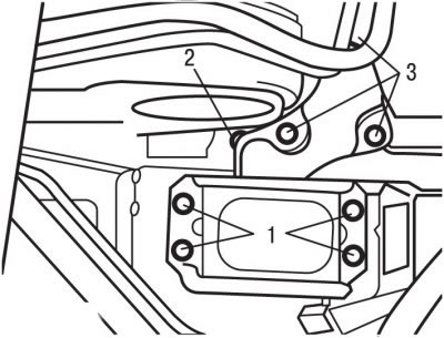
Figure 3.52. Location of bolts (1, 2, 3) for fastening the engine bracket
Remove bolts 1 and 3 (figure 3.52) engine bracket mounts.
Remove the right upper engine bracket.
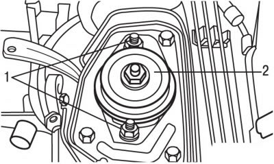
Figure 3.53. Location of bolts (1) and nuts (2) for fastening the left intermediate support of the power unit
Remove bolts 1 (figure 3.53) and nut 2 securing the left intermediate support of the power unit and remove the support.
Make sure all electrical wires, hoses, pipes and lines are disconnected from the engine.
Remove the power unit, being careful not to touch any surrounding components.
If necessary, disconnect the gearbox from the engine.
Installation
The engine is installed in the reverse order of removal, taking into account the following.
Replace with new self-locking nuts and bolts that were tightened by turning them to a certain angle, as well as sealing rings and gaskets.
Install the power unit in place.
Install the left intermediate support in place, then the right intermediate support. Insert the support mounting bolts and tighten bolts 1 and 2 (see Figure 3.52) torque 60 Nm, bolts 1 (see Figure 3.53) with a torque of 30 Nm and nut 2 with a torque of 65 Nm.
Disconnect the special tools from the engine and lower the jack with the platform.
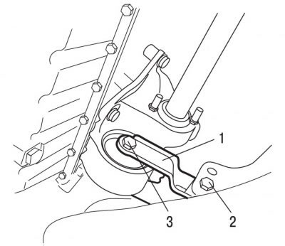
Figure 3.54. Location of engine mount reaction bracket mounting bolts: 1 - bracket; 2 - bolt, 55 Nm; 3 - bolt, 40 Nm
Install the reaction bracket 1 in place (figure 3.54) engine mounts and tighten the bracket mounting bolts to the appropriate torques.
Connect constant velocity joints to the gearbox.
Connect all contact connectors to the engine.
Connect the ground wire and secure it with a bolt.
Connect the connector to the oxygen concentration sensor.
Connect the coolant supply hoses to the heater radiator.
Install the clutch drive mechanism.
Install and bolt the air conditioning compressor.
Install the air conditioning condenser.
Install the radiator.
Install the exhaust manifold pipes and secure them with the bolts, tightening them to a torque of 25 Nm.
Install shock absorbing elements on the lower gearbox housing.
Further installation of the engine is carried out in the reverse order of removal, taking into account the following.
Install the accessory drive belt.
Fill the gearbox with oil.
Fill with coolant and bleed it.
Install the front wheels and secure them with bolts, tightening them to a torque of 90 Nm.
Perform programming of the engine management system computer.