



Lubricate the working surface of the main bearings with a thin layer of engine oil.
Install the crankshaft onto the cylinder block.
Install the thrust washers so that the grooved side faces the crankshaft.
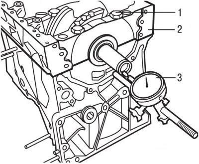
Figure 3.63. Measuring the crankshaft clearance: 1 - bolts, M11; 2 - main bearing cap housing; 3 - hour indicator
Check the axial play of the crankshaft by installing the main bearing cap housing 2 in place (figure 3.63) and secure it with 10 bolts 1, tightening them to a torque of 10 Nm.
Install a bracket with a dial indicator on the engine cylinder block so that the measuring tip of the indicator rests against the end of the crankshaft.
Move the crankshaft along the axis in one direction until it stops and set the indicator to 0. Move the crankshaft along the axis in the other direction until it stops and record the value on the indicator. The nominal crankshaft axial clearance is 0.06-0.15 mm. If the clearance exceeds the permissible value, thicker thrust washers must be installed.
Remove the bolts and the main bearing cap housing.
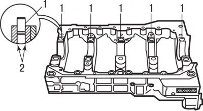
Figure 3.64. Location of centering bushings (1) in the main bearing cap housing and the places where they are secured with a special device (2)
Check for the presence of centering bushings 1 (figure 3.64) in the main bearing cap housing. If necessary, replace or install new centering bushings. Insert the centering sleeve halfway into the main bearing cap housing and use special tool 2 to secure them in this position.
Apply AUTOJOINT NOIR sealing compound around the perimeter of the main bearing cap housing.
Install the main bearing cap housing.
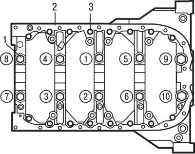
Figure 3.62. Location and tightening sequence (numbers in circles) m11 bolts (1) and M6 bolts (3) for fastening the main bearing cap housing (2)
Consistently (see Figure 3.62), tighten the main bearing cap housing bolts in several stages:
- 1st - tighten the M11 bolts to a torque of 10 Nm;
- 2nd - tighten the M6 bolts to 5 Nm;
- 3rd - unscrew the M11 bolts;
- 4th - tighten the M11 bolts to a torque of 10 Nm;
- 5th - tighten the M11 bolts to a torque of 20 Nm;
- 6th - tighten the M11 bolts to an angle of 70° ±5°;
- 7th - tighten the M6 bolts to 10 Nm.
After tightening the bolts, check that the crankshaft turns easily and smoothly.
Turn the engine crankshaft so that the piston of the 1st cylinder is at BDC.
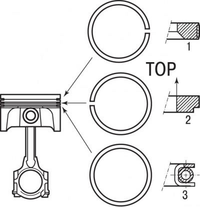
Figure 3.65. Location of piston rings and their ring joints on the piston: 1 - first compression piston ring; 2 - second compression piston ring; 3 - oil scraper piston ring
Install piston rings on the pistons. The "TOP" mark on the second compression piston ring must be directed towards the piston crown (figure 3.65). The lock of the second compression piston ring must be turned 180° in relation to the first compression ring. The oil scraper ring does not have a lock.
Before installing the piston into the cylinder, the piston rings must be compressed using a special sleeve or a tension band clamp.
Install the upper bearing of a predetermined class into the connecting rod and lubricate its working surface with a thin layer of motor oil.
Lubricate the cylinder surface with a thin layer of motor oil.
Install the piston with piston rings into the cylinder, ensuring that the special bushing or clamping band is pressed tightly against the cylinder block and positioned exactly in the center of the cylinder liner. The arrow on the piston should point towards the timing belt.
Use a hammer handle to insert the piston into the cylinder, making sure the oil scraper ring is installed correctly.
Turn the cylinder block over.
Install the lower bearing shell into the connecting rod cap and lubricate its working surface with a thin layer of motor oil.
Install the connecting rod cap and secure it with the bolts, tightening them to a torque of 23 N·m and then turning them further by an angle of (45±5)°. Pre-lubricate the bolts with a thin layer of engine oil.
Install the remaining pistons in the same manner.
Apply AUTOJOINT NOIR sealing paste to the mating surface of the front cover with the oil pump.
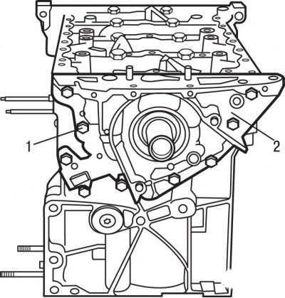
Figure 3.66. Location of bolts (1) securing the front cover (2) to the oil pump
Install the front cover 2 (figure 3.66) with an oil pump on the cylinder block.
Apply LOCTITE FRENETANCH to the threads of the front cover mounting bolts to prevent them from loosening.
Secure the front cover 2 with the oil pump using bolts, tightening them to a torque of 8 Nm.
Clean the front and rear crankshaft oil seal locations.
Lubricate the lips of the new oil seals with engine oil before installing them in place.
Using drifts, install the front and rear crankshaft oil seals.
Install and bolt the oil emulsion prevention plate.
Install and bolt the oil pickup with a new gasket and mesh filter.
Apply a uniform thin layer of AUTOJOINT NOIR sealing paste to the mating surface of the cylinder block with the oil pan.
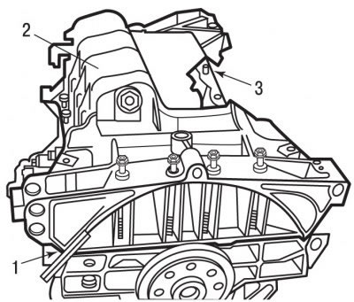
Figure 3.67. Location of the guide pin (3) of the oil pan (2) and the place where the metal ruler (1) is applied
Check the presence of guide pin 3 on the cylinder block (figure 3.67).
Install the oil pan 2.
Install the oil pan mounting bolts until the bolt heads contact the oil pan, but do not tighten the bolts.
Place a metal straight edge on the end of the cylinder block and, moving the oil pan, position it so that it is flush with the cylinder block.
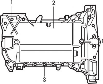
Figure 3.61. Location of bolts (1 and 3) for fastening the oil pan (2)
Tighten bolts 1 and 3 (see Figure 3.61) oil pan fastening torque 8 Nm.
Use a tap to clean the threads in the crankshaft for mounting the flywheel.
Clean the mating surfaces of the crankshaft and flywheel.
Install the flywheel and screw in the new bolts until the bolt heads contact the flywheel.
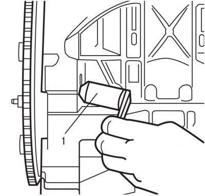
Figure 3.59. Installing a special device to prevent the flywheel from turning
While turning the flywheel, align the blind hole on the flywheel with the hole in the cylinder block, and use special tool 1 (see Figure 3.59) lock the flywheel from turning.
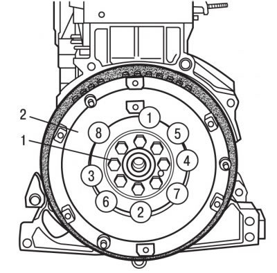
Figure 3.68. Tightening sequence (numbers in circles) flywheel mounting bolts (1) (2)
In the sequence shown in the figure 3.68, tighten the flywheel mounting bolts to a torque of 20 Nm, then turn them further in the same sequence by an angle of (26±3)°.
Remove the device that prevents the flywheel from turning.
Turn the crankshaft to a position where the pistons are at the middle of their stroke.
Check for the presence of centering bushings in the cylinder block.
The new cylinder head gasket must be removed from its packaging immediately before installation.
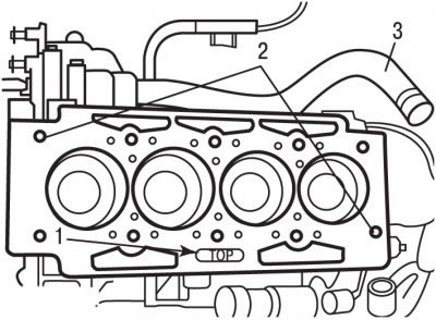
Figure 3.69. Location of centering bushings (1) and the "TOP" inscription (2) on the cylinder head gasket and the rigid pipe (3) of the cooling system
Install the gasket on the guide bushings 1 (figure 3.69), in this case, the inscription "TOP" should be directed towards the head and located on the side of the oil filter.
The source is located on the website www.peugeotbook.ru
Install the cylinder head.
Before reusing bolts, measure the length of the bolts to the base of the head, which should be (144.5±0.5) mm.
Apply a thin coat of MOLYKOTE G RAPID PLUS grease to the threads of the cylinder head bolts, insert the bolts and tighten them by hand.

Figure 3.70. Cylinder head bolt tightening sequence
In the sequence shown in the figure 3.70, tighten the cylinder head bolts in several stages:
- 1st - tighten to 15 Nm;
- 2nd - tighten to 50 Nm;
- 3rd - unscrew the bolts one turn (360°);
- 4th - tighten to 20 Nm;
- 5th - turn to an angle (285±5).
There is no need to further tighten the cylinder head mounting bolts.
If removed, reinstall the hydraulic lifters, stoppers and camshafts.
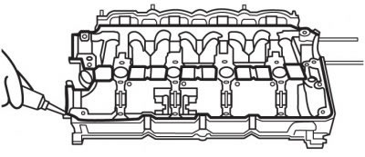
Figure 3.71. Places where AUTOJOINT NOIR sealing paste is applied to the camshaft cover housing
Apply AUTOJOINT NOIR sealing paste to the mating surface of the camshaft cover housing in an even layer with a diameter of 3.5 mm (figure 3.71).
Install the camshaft cover housing onto the cylinder head.
Note: To ensure accurate installation of the cover housing, rotate the camshafts.
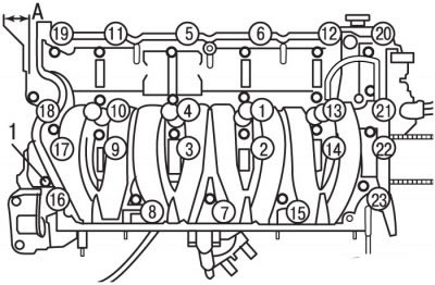
Figure 3.72. Tightening sequence (numbers in circles) bolts (1) for fastening the camshaft cover housing and the place (A) for measuring the camshaft protrusion
Check the camshaft protrusion A (figure 3.72) from the cylinder head, which should be within (8.0±2.0) mm.
Install bolts 1 and screw them in until the bolt heads contact the camshaft cover housing.
In the sequence shown in the figure 3.72, tighten the camshaft cover housing mounting bolts in several stages:
- 1st - tighten to 5 Nm;
- 2nd - tighten to 10 Nm.
Check for the presence of centering bushings and install the water pump.
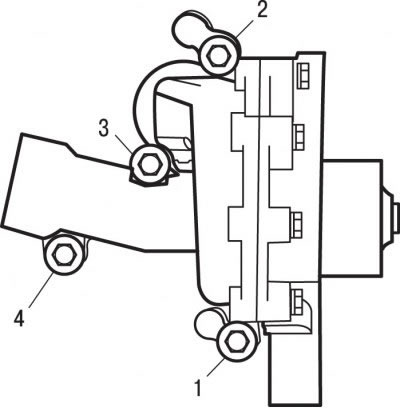
Figure 3.73. Tightening sequence (numbers in circles) water pump mounting bolts
In the sequence shown in the figure 3.73, tighten the water pump mounting bolts in several stages:
- 1st - tighten to 3 Nm;
- 2nd - tighten to 8 Nm;
- 3rd - tighten to 14 Nm.
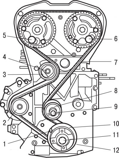
Figure 3.74. Timing drive elements: 1 - a special device for fixing the engine crankshaft from turning; 2 - water pump; 3 - tension roller; 4 - bolt; 5, 6 - special devices for fixing camshafts from turning; 7 - toothed belt; 8 - guide roller; 9 - bolt; 10 - flange; 11 - central bolt; 12 - toothed belt pulley
Install the tension roller 3 of the toothed belt and secure it with bolt 4 (figure 3.74).
Install the rear timing belt covers.
Install the guide roller 8 of the toothed belt and secure it with bolt 9.
Install the toothed belt pulley 12, flange 10 on the crankshaft and screw in the central bolt 11.
Install the timing belt pulley onto the exhaust camshaft. While holding the camshaft by the flat with a wrench to prevent it from turning, screw in the pulley mounting bolt and tighten it to a torque of first 30 N·m, and then 75 N·m.
Similarly, install and secure the timing belt pulley on the intake camshaft.
Using special tools 5 and 6, secure the camshafts from turning.
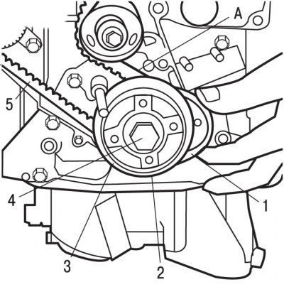
Figure 3.75. Installing the toothed belt on the crankshaft pulley: 1 - a special device for fastening the toothed belt to the crankshaft pulley; 2 - toothed belt pulley; 3 - flange; 4 - central bolt; 5 - toothed belt; A - branch of the toothed belt
Check that the center bolt 4 (figure 3.75) the pulley fastenings are not tightened and pulley 2 can rotate slightly.
Install toothed belt 5 on crankshaft pulley 2.
Using special tool 1, secure toothed belt 5 to crankshaft pulley 2.
Pull the belt branch A so that the crankshaft pulley 2 turns until it stops on the flange 3.
Install the timing belt of the gas distribution mechanism sequentially on the guide roller 8, the camshaft pulley of the intake valves, the camshaft pulley of the exhaust valves, the water pump 2 and the tension roller 3 (see Figure 3.74).
Remove special tool 1 (see Figure 3.75).
Remove special tools 5 and 6 (see Figure 3.74), locking camshafts from turning.
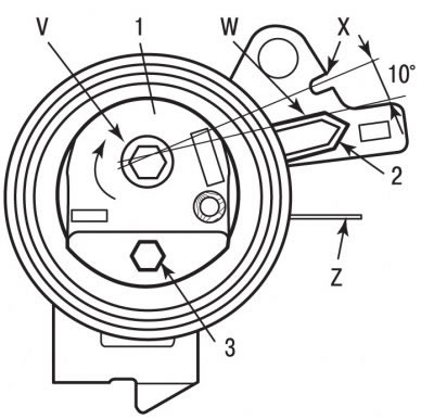
Figure 3.76. Positions of the tension roller when adjusting the toothed belt tension: 1 - tension roller; 2 - pointer; 3 - hex head; V - direction of rotation of the tension roller; W - conditional line of belt pre-tensioning; X - notch for final belt tensioning; Z - connecting plane of the cylinder head
For hexagon 3 (figure 3.76) turn tension roller 1 counterclockwise to a position where pointer 2 aligns with the conventional line W.
Attention! When combining pointer 2 (see Figure 3.76) with the imaginary line W, it must pass through the notch X at an angle of at least 10°. Otherwise, replace the tension roller or the tension roller and timing belt.
Then for hexagon 3 (see Figure 3.76) turn tension roller 1 in the direction of arrow V until pointer 2 aligns with recess X.
Caution! The pointer must not move beyond the notch X, otherwise repeat the timing belt tensioning operations.
Tighten the tension roller mounting bolt to 20 Nm.
Caution! The tension roller should not turn when tightening its mounting bolt; otherwise, repeat the timing belt tensioning operations. The hexagon for turning the tension roller must be located below the connecting plane of the cylinder head Z (see Figure 3.76). Otherwise, replace the tension roller or tension roller and timing belt.
Turn the crankshaft engine 10 revolutions, while no pressure or external influences should be applied to the timing belt.
Special devices 5 and 6 (see Figure 3.74) secure the intake camshafts from turning.
Check that pointer 2 is aligned with notch X. If not, repeat the timing belt tensioning operations.
Special device 1 (see Figure 3.74) fix the engine crankshaft from turning.
Tighten the center bolt securing the timing belt pulley to the crankshaft:
- bolt with steel washer (golden color) torque of 40 Nm and turn it further at an angle of (53±4)°;
- bolt with annealed steel washer (metallic color) torque of 40 Nm and turn it further at an angle of (40±4)°.
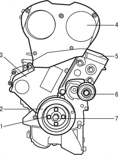
Figure 3.60. Location of engine parts: 1 - pulley mounting bolt; 2 - auxiliary drive belt pulley; 3 - lower toothed belt cover; 4 - upper toothed belt cover; 5 - engine mounts; 6 - tension roller; 7 - central bolt for fastening the toothed belt pulley to the crankshaft
Install the top 4 in place (see Figure 3.60) and lower 3 timing belt casings.
Install engine mount cushion 5 and tension roller 6.
Install pulley 2 of the accessory drive belt and secure it with bolts 1.

Figure 3.77. Location of bolts (1) for fastening the cylinder head covers (2), the current phase sensor in the cylinder (3) and bolts (4) for fastening the ignition coil unit (5)
Install the cylinder head covers 2 (figure 3.77).
Install the current phase sensor in cylinder 3.
Install the ignition coil block 5 and secure it with bolts 4.
Install the mounting bolts and screw them in until the bolt heads contact the cylinder head covers.
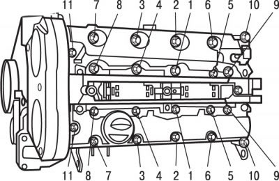
Figure 3.78. Tightening sequence (numbers in circles) cylinder head cover mounting bolts
In the sequence shown in the figure 3.78, tighten the cylinder head cover bolts in several stages:
- 1st - tighten to 5 Nm;
- 2nd - tighten to 15 Nm.
Install the exhaust manifold gasket or new heat shield.
Install the exhaust manifold and secure it with nuts, tightening them to a torque of 35 Nm.
Install the coolant outlet block gasket.
Replace the water pump coolant outlet block connector on the coolant outlet block.
Install the water pump coolant outlet block connecting pipe to the coolant outlet block as an assembly.
Install a new gasket on the catalytic converter.
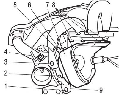
Figure 3.79. Fastening elements on the exhaust manifold side: 1, 2, 3 - bolts; 4 - exhaust gas recirculation tube; 5, 8 - nuts; 6 - welded bolt; 7 - heat shield; 9 - clamp
Turn the clamp 9 (figure 3.79) so that it can be put on the welded bolt 6.
Install the EGR pipe 4 and secure it with a clamp.
Screw nut 5 onto welded bolt 6.
Screw on nuts 8.
Screw in bolts 3, 2 and 1. Tighten bolt 2 to 4 Nm.
Install heat shield 7 and secure it with bolts.
Install oxygen sensors.
Install the exhaust gas recirculation valve.
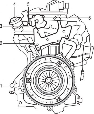
Figure 3.55. Components that must be removed first when disassembling the EW10J4 engine: 1 - clutch pressure plate; 2 - plate on the coolant outlet block; 3 - high pressure fuel line; 4 - valve; 5 - fuel return pipe; 6 - high pressure fuel supply pump
Remove plate 2 (see Figure 3.55) on the coolant outlet block.
Lubricate the splines in the clutch driven disc hub with a thin layer of special grease based on molybdenum disulfide.
Install the clutch driven disc onto the flywheel.
Install the clutch assembly, aligning the holes in the clutch housing with the flywheel guide pins. When reinstalling a previously removed clutch pressure plate, check that the marks made before removal are aligned.
Tighten the clutch mounting bolts so that the driven clutch disc is pressed down, but at the same time can still move sideways.
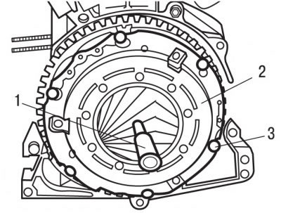
Figure 3.80. Clutch installation: 1 - centering mandrel; 2 - clutch housing; 3 - bolts, 20 Nm
Using a special centering mandrel 1 (figure 3.80) or the old primary shaft of the gearbox, center the clutch disc relative to the flywheel.
After centering the driven disk, gradually tighten bolts 3 of the clutch housing 2 diagonally to a torque of 20 N·m.
Remove the mandrel from the driven disk.
Install the knock sensor and secure it with the bolt, tightening it to a torque of 20 Nm.
Reinstall the oil filter support and oil filter.
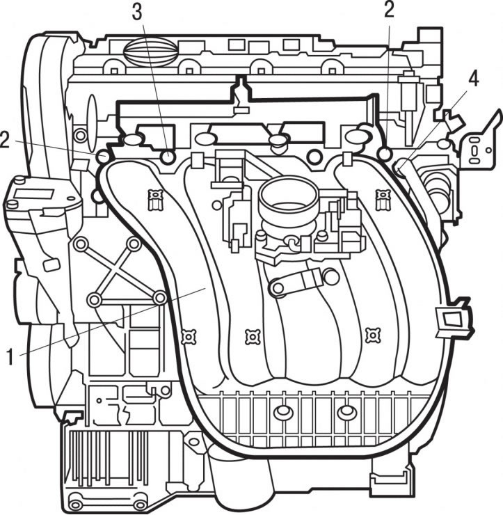
Figure 3.81. Location of the air distributor (1) together with the fuel injection rail, nuts (2) and bolts (3) for its fastening and the cooling system pipe (4)
Install air distributor 1 (figure 3.81) together with the fuel injection rail and secure with nuts 2 and bolts 3, tightening them to a torque of 20 Nm.
Connect the cooling system hose and secure it with clamp 4.