
Attention! Replace all clamps and clamps that are damaged or cut during removal with new ones when installing the head of the block. When replacing the block head, fill the cooling system with fresh coolant.
Removing
Drain the coolant from the engine cooling system.
Disconnect the exhaust pipe from the exhaust manifold.
Remove the decorative casing from the engine.
Depressurize the fuel system by connecting special tool 0141-T1 to the SHRADER valve and collect the gasoline in a container.
Disconnect the terminals from the battery.
Disconnect the electrical connectors from the throttle assembly.
Disconnect the fuel vapor trapping tubes from the fittings.
Disconnect the flexible clutch cable.
Disconnect the pipe from the exhaust gas recirculation system.
Turn out a bolt of fastening of a tube of the indicator of level of oil.
Remove the air intake duct.
Remove the accessory drive belt.
Remove the toothed belt.
Remove the toothed belt tensioner.
Install the right intermediate engine mount.
Turn out bolts of fastening of covers of heads of the block of cylinders.
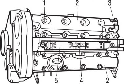
Pic. 3.77. Bolt location (1) fastening of covers of heads of the block of cylinders (2), sensor of the current phase in the cylinder (3) and bolts (4) fastening of the block of ignition coils (5)
Remove the current phase sensor in cylinder 3 (see fig. 3.77).
Remove the cylinder head covers 2.
Turn out bolts 4 and remove the block of compact ignition coils 5.
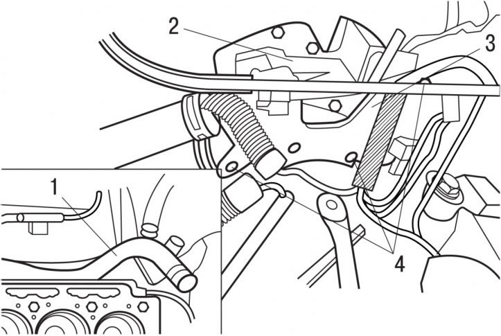
Pic. 3.82. Rigid tube location (1) connecting the water pump to the block (2) coolant outlet, supports (3) wiring harness and bolts (4)
On the flywheel side, loosen bolts 4 (pic. 3.82).
Move the wiring harness support 3 aside.
Remove the rigid tube 1 connecting the water pump to the coolant outlet block 2.
Move the coolant outlet block 2 away from the cylinder head.
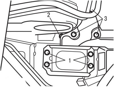
Pic. 3.52. Bolt location (1, 2, 3) engine bracket mounts
Loosen bolt 2 as far as possible (see fig. 3.52).
Pic. 3.70. Cylinder head bolt tightening sequence
In the reverse order to tightening, gradually loosen and then completely unscrew the cylinder head bolts (see fig. 3.70).
Before removal of a head of the block of cylinders be convinced that all hoses, pipelines and contact sockets are disconnected from it.
Using a lifting gear, remove the cylinder head together with the exhaust manifold and place it on a soft base.
Remove the cylinder head gasket.
Preparing the block head for installation
On the camshafts, clean the seal contact surfaces.
The mating surfaces of the head and cylinder block must be perfectly clean. Use a hard plastic or wooden scraper to clean them. Be careful when cleaning as aluminum alloy is very easy to damage. Make sure that carbon deposits do not get into the channels of the lubrication and cooling system. This is especially important for the lubrication system, as deposits can block the oil supply to engine parts. Clean channels if necessary.
Check the mating surfaces of the head and cylinder block: they should not have nicks, deep scratches or other damage. Small defects can be eliminated by machining. In case of significant defects, the parts must be replaced.
Using a metal ruler and feeler gauge, check the flatness of the mating surfaces.
If the flatness deviation exceeds 0.05 mm, regrind the head.
Clean the threads of the cylinder head bolt holes.
Clean the bolt holes in the block. Be aware that driving a bolt into an oil-filled hole may rupture the block due to hydraulic pressure.
Before reusing the bolts, measure the length of the bolts to the base of the head, which should be 147.0 mm.
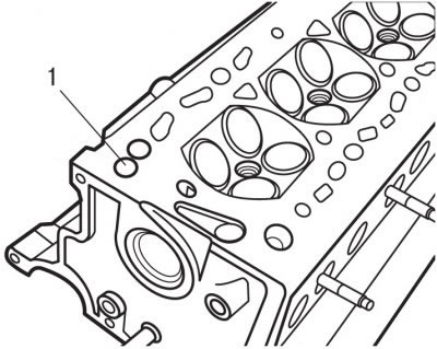
Pic. 3.83. Location of the anti-return valve (1) in the cylinder head
Replace the anti-return valve in the cylinder head 1 (pic. 3.83).
Installation
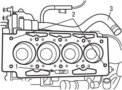
Pic. 3.69. Location of centering sleeves (1) and inscriptions «TOP» (2) on the cylinder head gasket and rigid tube (3) cooling systems
Check for presence of centering sleeves 1 (see fig. 3.69) in the cylinder block.
Check the condition of the O-rings of the rigid tube 3 and install the tube in the water pump.
A new cylinder head gasket must be removed from the packaging immediately before installation.
Install the gasket on the guide bushings 2, while the inscription 1 «TOP» should be directed towards the head and located on the side of the oil filter.
Install the coolant outlet block to the cylinder head.
Install tube 3 into the coolant outlet block.
Install the cylinder head with the toothed belt pulley fixed.
Lightly coat the threads of the cylinder head bolts with MOLYKOTE RAPID PLUS grease, insert the bolts and hand-tighten.
Consistently (see fig. 3.70), tighten the cylinder head bolts in several stages:
- 1st - tighten with a torque of 15 Nm;
- 2nd - tighten with a torque of 50 Nm;
- 3rd - unscrew the bolts one turn (360°);
- 4th - tighten with a torque of 20 Nm;
- 5th - tighten the corner (285±5) °.
Further installation of a head of the block of cylinders spend in sequence, return to removal, taking into account the following.
Fill the spaces under the hydraulic valve lifters with fresh engine oil.
Tighten bolt 2 (see fig. 3.52) torque 45 Nm.
Install the cylinder head covers.
Install the current phase sensor in cylinder 3 (see fig. 3.77).
Install the ignition coil unit 5 and secure it with bolts 4.
Establish fastening bolts and screw them before contact of heads of bolts with covers of heads of the block of cylinders.
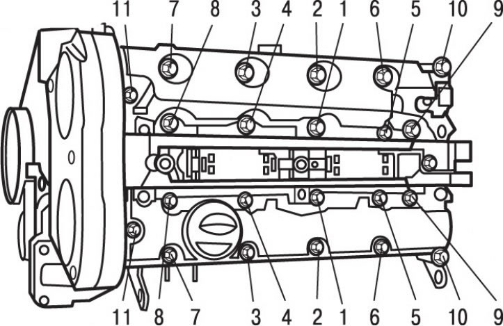
Pic. 3.78. Tightening sequence (numbers in circles) cylinder head cover bolts
Consistently (see fig. 3.78), tighten the cylinder head cover bolts in several stages:
- 1st - tighten with a torque of 5 Nm;
- 2nd - tighten with a torque of 15 Nm.
Remove the right intermediate engine mount.
Install the toothed belt and adjust its tension.
Install the accessory drive belt.
Further installation of a head of the block of cylinders spend in sequence, return to removal.
Fill with coolant and bleed air from it.