
Removing
Disconnect the wire from the negative battery terminal.
Remove the right mudguard.
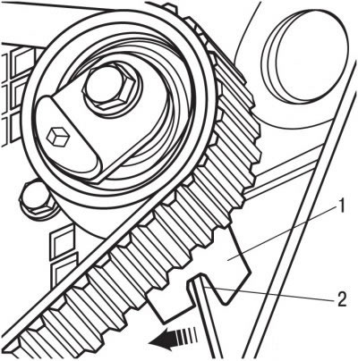
Attention! Chalk, marker or paint mark the direction of rotation of the toothed belt. If the toothed belt rotates in the opposite direction during installation, this will lead to its destruction.
Remove the accessory drive belt.
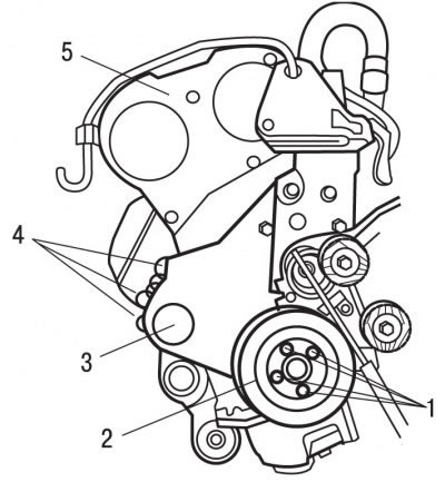
Pic. 3.86. Removing the lower and upper casings of the toothed belt: 1, 4 - bolts; 2 - auxiliary drive belt pulley; 3 - lower casing of the toothed belt; 5 - the top casing of a gear belt
Remove bolts 1 (pic. 3.86) and remove the pulley 2 of the accessory drive belt.
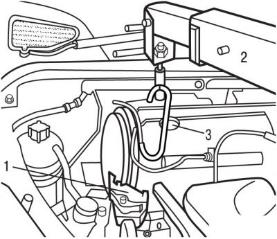
Pic. 3.87. Location of the right intermediate engine mount (1) and captures (3) lifting mechanism (2)
Hook Grips 3 (pic. 3.87) lifting gear 2 by the lifting eye of the motor and lift it up so that the weight of the motor is supported by the lifting gear.
Remove the right intermediate support of the engine 1.
Remove the top cover 5 (see fig. 3.86) toothed belt.
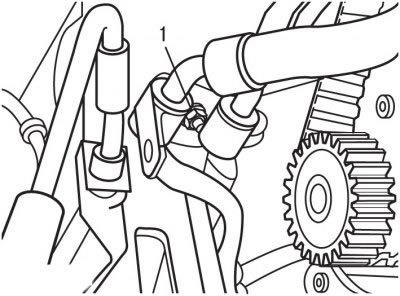
Pic. 3.88. Bolt location (1) fastening of hoses of the hydraulic amplifier of a steering
Remove bolt 1 (pic. 3.88) securing the power steering hoses, move the hoses to the side and secure them in this position.
Remove the bottom cover 3 (see fig. 3.86) toothed belt, being careful not to damage it. Do not loosen screws 4.
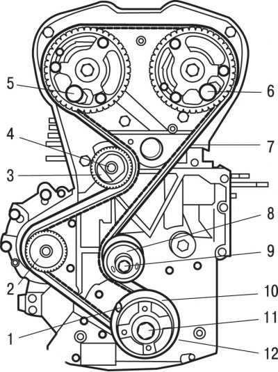
Pic. 3.74. Elements of the gas distribution mechanism drive: 1 - a special device for fixing the engine crankshaft from turning; 2 - water pump; 3 - tension roller; 4 - bolt; 5, 6 - special devices for fixing camshafts from turning; 7 - toothed belt; 8 - guide roller; 9 - bolt; 10 - flange; 11 - central bolt; 12 - toothed belt pulley
Special tool 1 (see fig. 3.74) secure the engine crankshaft from turning.
Use special tools 5 and 6 to secure the camshafts from turning.
Loosen the bolt 4 as much as possible and release the tension roller bracket 3 from the lug of the cylinder block to increase its freedom of movement.
Remove toothed belt 7.
Installation
Attention!
- 1. Do not twist or bend the toothed belt. Do not expose the toothed belt to oil, coolant or fuel.
- 2. If the outer surface of the toothed belt is significantly worn or stratified, check the condition of the treadmills of the guide and tension rollers.
- 3. If there are any defects on the toothed belt, replace it.
Check that the guide and idler rollers rotate smoothly and evenly.
If the guide roller has been replaced, tighten the roller mounting bolt to 35 Nm.
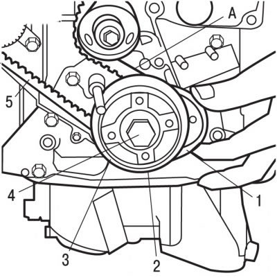
Pic. 3.75. Installing the toothed belt on the crankshaft pulley: 1 - a special tool for fastening the toothed belt to the crankshaft pulley; 2 - toothed belt pulley; 3 - flange; 4 - central bolt; 5 - toothed belt; A - toothed belt branch
Install toothed belt 5 on crankshaft pulley 2 (see fig. 3.75).
Using the special tool 1, fasten the toothed belt 5 to the crankshaft pulley 2.
Install the timing belt in sequence on the guide pulley 8, the intake camshaft pulley, the exhaust camshaft pulley, the water pump 2 and the tension pulley 3 (see fig. 3.74).
Remove special tool 1 (see fig. 3.75).
Remove special tools 5 and 6 (pic. 3.74), fixing the camshafts from turning.
Timing belt tension adjustment operations must be performed on a cold engine.
Pic. 3.89. Bracket installation (1) tide tension roller (2) cylinder block
Install the idler pulley bracket 1 (pic. 3.89) on the tide 2 cylinder blocks.
Remove the special tool 1 holding the toothed belt 5 on the crankshaft pulley 2 (see fig. 3.75).
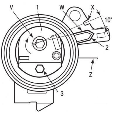
Pic. 3.76. Positions of the tension roller when adjusting the tension of the toothed belt: 1 - tension roller; 2 - pointer; 3 - hex head; V - the direction of rotation of the tension roller; W - conditional belt pretensioning line; X - notch for the final tension of the belt; Z - connecting plane of the cylinder head
For hex head 3 (see fig. 3.76) turn the tension roller 1 to the position where pointer 2 is aligned with the conditional line W, while the tension of the toothed belt will be maximum.
Attention! When pointer 2 is aligned (see fig. 3.76) with an imaginary line W, it must pass through the notch X at an angle of at least 10°. Otherwise, replace the tension roller or tension roller and toothed belt.
Install calibrated pin 0189-J to lock the dynamic tensioner roller in position.
For hex head 3 (see fig. 3.76) turn the tension roller in the opposite direction of the arrow until the slider contacts the pin. This operation allows you to set the pointer 2 opposite the notch X, i.e. to the position of the nominal tension of the toothed belt.
Attention! It is forbidden to turn the tension roller a full turn. The pointer must not move beyond the notch X, otherwise repeat the operations for tensioning the toothed belt.
Tighten the tension roller mounting bolt to 20 Nm.
Attention! The tension roller must not rotate when tightening its fastening bolt, otherwise repeat the operations for tensioning the toothed belt.
The hexagon for turning the tensioning roller must be below the connecting plane of the cylinder head Z (see fig. 3.76). Otherwise, replace the tension roller or tension roller and toothed belt.
Remove the special devices that fix the camshafts and the flywheel from turning.
Turn the engine crankshaft 10 revolutions, while no pressure and no external influences should be applied to the toothed belt.
Check that the pointer is 2 (see fig. 3.76) is aligned with notch X. Otherwise, repeat the toothed belt tensioning operations.
Establish the bottom casing of a gear belt 3 (see fig. 3.86).
Install the accessory drive belt pulley and secure with bolts to 20 Nm.
Establish the top casing 5 a gear belt.
Reinstall the hydraulic power steering hoses and secure them with bolt 1 (see fig. 3.88).
Install the right intermediate engine mount 1 (see fig. 3.87).
Unhook the grip 3 of the hoist 2 from the engine.
Install the accessory drive belt.
Further installation is carried out in the reverse order of removal.
Connect the wire to the negative terminal of the battery.