



- Disconnect the battery.
- Raise the right front wheel and place the right side of the car on stands.
- Remove the plastic fender from the wheel arch. To protect the alternator from diesel fuel, cover it with a thick cloth.
- Remove the upper timing belt cover by first pushing it forward and then pulling it up.
- Remove the air distribution box from the top of the cylinder head.
- Unscrew the union nuts on the injectors and on the high-pressure fuel pump and remove the entire set of pipes. For reliability, mark the tubes.
- On the right side of the pump, disconnect the idle speed increase device cable. Disconnect the fuel and return fuel hoses from the injectors and pump.
- Disconnect the wire from the pump stop device (on the right side of the pump).
- Engage the gear and turn the engine to a position where it is possible to screw both locking bolts (8x30 mm) at locations (3) in Fig. 288 into the pump drive gear. Screw the bolts in completely without tightening them. To make it easier to turn the engine, you can unscrew the plug of the hole for checking the top dead center (1) of the fourth cylinder in Figure 289.
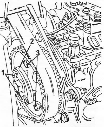
Figure 288. Toothed pulley of the high-pressure fuel pump. 1. Flange bolts; 2. Removable flange; 3. Locking bolts (thread M8x30 mm)
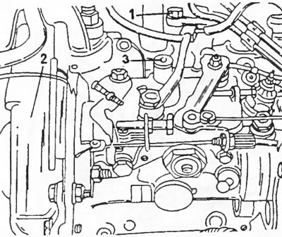
Figure 289. Location of the top dead center inspection hole plug (1) and the timing belt cover (2) on the high-pressure fuel pump. The plug (3) closes the hole for adjusting the high-pressure fuel pump.
Loosen the toothed pulley mounting nuts until the pulley begins to move, that is, until the toothed shaft begins to slowly come off the shaft. Insert a holding tool into the timing pulley in the same manner as used to lock the camshaft timing pulley. Use an open-end wrench to loosen the nuts.
While still holding the toothed pulley, remove both bolts in front of the pulley ("1" in Figure 288).
Remove the three pump mounting bolts and the rear pump mounting bolts and move the pump away from the engine. Completely loosen both flange bolts, remove the flange and completely remove the pump by loosening the toothed pulley nuts.
The fuel pump is installed in the following sequence:
- Insert the bolt (1) and the screw (2) in Fig. 290 into the pump console (3).
- Insert a key into the pump shaft and place the toothed pulley onto the shaft, engaging with the key. Be sure to check the engagement of the pulley with the key. This can be checked using a small mirror. Place the pump in the correct mounting position and tighten the shaft nut to a torque of 50 Nm. Due to lack of space, it is difficult to fit the wrench head and torque wrench. That is, here you need to be able to determine the tightening moment well by eye. Install the flange and tighten both its bolts to a torque of 10 Nm.
- Screw on the pump mounting nuts from the flange side and install the rear mount without tightening it yet. Remove both locking bolts from the pump toothed pulley.
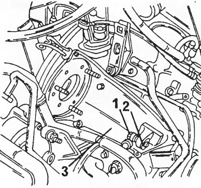
Figure 290. Mounting console (3) of the high-pressure fuel pump. Before installing the pump, the bolt (1) with washer (2) must be inserted.
After this, the high pressure fuel pump is adjusted in accordance with the following instructions, however, it should be noted that for normal adjustment of injection timing it is necessary to have some experience with high pressure fuel pumps. To make adjustment easier, a brief description of the high pressure fuel pump adjustment principle is given below.
Each pump rotor has a rounded neck "c" in Figure 291, the position of which is precisely fixed during manufacture. The start of pump injection is determined by the dimension "X" when the piston of the fourth cylinder is in the top dead center position. This size is engraved on the lever on the top side of the pump. The dimensions are not the same on all pumps; the dimensions differ by tenths.
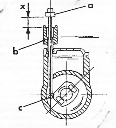
Figure 291. Sectional view of high-pressure fuel pump (see text).
The following description also assumes that the pump is installed. In this case, the description of a number of works is omitted.
- If the pump has been turning in the meantime, set it to the top dead center position of the fourth cylinder by inserting a rod from the rear of the cylinder block and two bolts into the toothed pulley of the high-pressure fuel pump (see the corresponding pictures).
- Remove the glow plug from the fourth cylinder.
- Remove the plug (3) shown in Figure 289 from the high-pressure fuel pump and insert the adjustment pin of device 0117AM shown in Figure 291. Pin "a" must be attached to tube "b". If this is not the case, crank the crankshaft. These works should have already been carried out when the pump was installed. When checking the injection timing, install the devices shown in Figure 292 on the pump, reset the dial indicator scale, paying attention to the position of the small arrow.
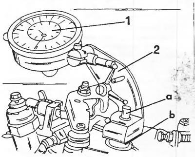
Figure 292. Installation of measuring instruments on the high-pressure fuel pump. Pin "a" and tube "b" correspond to the designations in Figure 291. 1. Arrow indicator; 2. Dial indicator stand
Turn the crankshaft until the indicator arrow starts to move. After this, insert the flywheel locking rod as shown in Figure 293. Please note that both ends of the rod are different and the rod must be inserted exactly as shown in the figure.
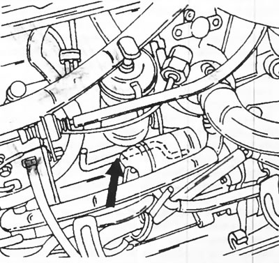
Figure 293. Insert the locking rod (arrow) from the rear of the engine.
Take a reading from the dial indicator scale. it must match the value engraved on the rod on the top side of the pump (for example 06.94). If the value differs from the specified value within plus/minus 0.04 mm, no adjustment is required; if this tolerance is exceeded, the pump should be adjusted.
Depending on whether the pump is already installed or is currently being installed, the pump adjustment work is performed differently:
- If the pump is screwed on, (Unscrew the front mounting nuts and the rear support. Loosen the union nuts of the injection pipes. Do not remove the alternator cover. If the pump is installed, loosen the nuts enough to allow the pump to rotate.
- In both cases, press the pump away from the engine until it stops in the flange slots.
- Slowly move the pump towards the engine until the readings on the dial gauge become equal to the specified value.
- Without turning the pump, tighten the three nuts (2) in Figure 294 to a torque of 20 Nm. At the other end, tighten the nut (3) to a torque of 23 Nm.
- Remove the locking rod from the rear of the engine and turn the crankshaft exactly two revolutions.
- Check the adjustment in the manner described above. Remove the adjusting tools and screw in the plug (1) in Fig. 294.
- Connect the injection pipes. Tighten the union nuts to a torque of 20 Nm.
- Screw in the glow plug of the fourth cylinder with a tightening torque of 22 Nm.
- Lower the car.
- Start the engine. Check engine operation and possibly make additional adjustments.
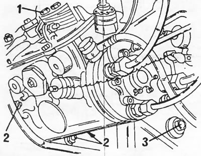
Figure 294. High pressure fuel pump. To install the measuring device shown in Figure 292, unscrew the plug (1). The front nuts (2) and the rear nut (3) have different tightening torques.