



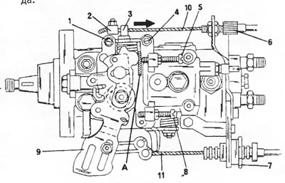
Figure 302. Adjusting the Bosch high-pressure fuel pump. References to numerical and letter designations are provided in the text.
Control of the operation of the idle speed increase device
- Check on a cold engine that the lever (3) is on the stop by pressing it in the direction of the arrow on the bolt (1).
Adjusting the idle speed increase device
[Source of the article is website: Peugeotbook.ru]
- If it is necessary to adjust the cable (10) using the cable adjuster (2), the cable sheath (6) must be tensioned accordingly.
Checking the operation of the idle speed increase device - the engine is warm
- Warm up the engine to operating temperature and check that the idle speed increase control cable (11) on the front side of the pump is loose (This is the cable coming from the thermostat capsule, also shown in Figure 283, position 3). Adjusting the idle speed increase device when the engine is warm
- If the cable has moved no more than 6 mm, check the operation of the temperature switch on the outlet fitting of the cooling system. The rope travel is indicated by the arrows in Figure 303 and can be measured at the indicated location.
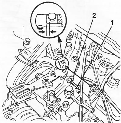
Figure 303. The free play of the cable is measured at the indicated location between the two arrows. The two adjusting bolts are marked (1) and (2).
Accelerator cable
- Turn off the engine. Have an assistant fully depress the accelerator pedal and check that the lever (9) rests against the stop screw (8). If it doesn't, adjust the accelerator cable at point "7." The lever (9) should rest against the stop screw (5).
Idle speed adjustment
- Loosen the screw (5) so that the lever (9) moves away from the screw surface. After loosening the lock nut with screw (4), set the engine speed within 750 + 50 rpm. Tighten the lock nut.
Residual flow adjustment
- Insert a 1.0 mm feeler gauge into location "A" between the lever (9) and the stop screw (5). After loosening the lock nut, adjust the stop screw so that the idle speed increases by 50 rpm.
- To adjust the idle speed increase device, press the lever (5) against the stop (1) and, if necessary, set the stop so that the speed is 950 ±50 rpm.
- The adjustment details are also explained in Figure 304. The figure also shows the place where the feeler gauge is inserted.
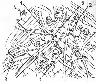
Figure 304. Residual flow adjustment. Correctly adjusted speed prevents the engine from stalling. 1. Accelerator lever; 2. Idle speed adjusting screw; 3. Residual flow adjustment screw; 4. Idle speed increase adjusting screw; 5. Lever