



Table of contents: Removal 🠇 Installation 🠇
Removal
1. Disconnect the ground cable from the battery (see "Disconnecting the battery").
2. Remove the accessory drive belt as described in chapter 1A.
3. On 1.9L DW series diesel engines, loosen the clamp in the center of the engine cover and remove the mounting screw on the right side. Remove the engine cover. On 2.0L diesel engines, rotate the four plastic fasteners 90° and remove the engine cover (Figure 8.3. a-d).
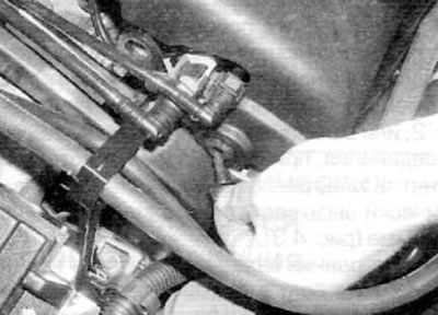
Figure 8.3, a. On 1.9L DW diesel engines, remove the fasteners on the right side...
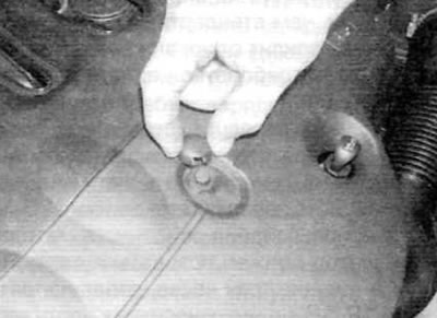
Figure 8.3, b....and the upper plane of the engine cover...
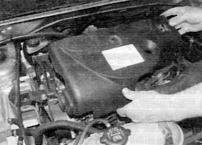
Figure 8.3, c....then remove the cover from the engine
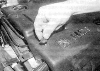
Figure 8.3, d. On 2.0L diesel engines, rotate each lock 90° to release...
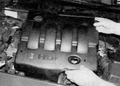
Figure 8.3, d....then remove the engine cover
4. To facilitate access to the alternator on models with power steering, remove the power steering pump mounting bolt (see chapter 10). Move the pump to the side, being careful not to lose the spacer element (if applicable) from the rear support (Figure 8.4, a-c). Tie the pump to the vehicle body/engine to prevent excessive deformation of the hydraulic lines/hoses. Note: There is no need to disconnect the lines/hoses from the pump. Release the pipes/hoses from all clamps to prevent them from becoming deformed.
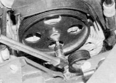
Figure 8.4, a. Remove the front power steering pump mounting bolts...
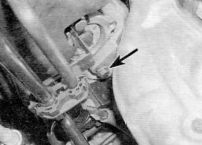
Figure 8.4, b....and the rear support bolt (marked with an arrow)...
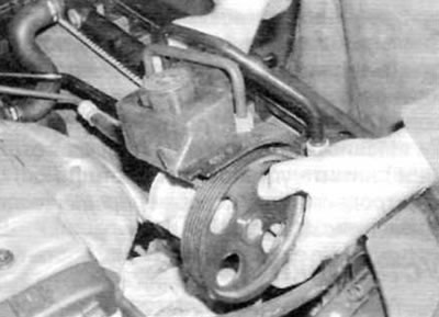
Figure 8.4, c....and then move the power steering pump to the side (a gasoline engine is shown)
5. Depending on the engine and equipment installed, either remove the three bolts and accessory belt tensioner, or remove the bolts and accessory belt idler pulley bracket.
6. Remove the rubber cover from the alternator terminal(s), then loosen the retaining nut and disconnect the wiring from the rear of the alternator (figure 8.6, a, b).
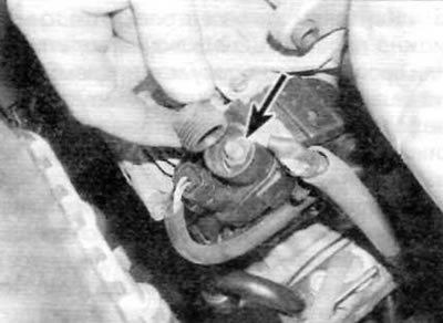
Figure 8.6, a. Remove the rubber cover, then unscrew the nut (marked with an arrow)...
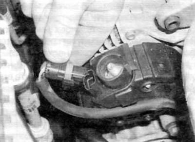
Fig. 8.6, b....and disconnect the electrical connector on the generator (a gasoline engine is shown)
7. Remove the generator mounting bolts and, if applicable, the adjuster bolt bracket mounting bolt to the generator (figure 8.7). Please note that on some models the left bolts act as centering bolts and have a spacer and cone built into them. To access the lower left bolt, remove the air conditioning compressor mounting bolt (if applicable) and move it to the side. Do not disconnect the refrigerant lines.
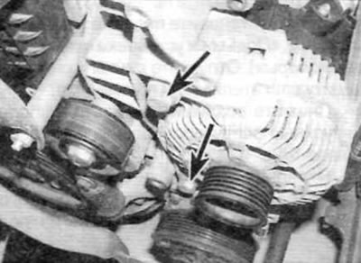
Figure 8.7. Generator front mounting bolts (marked with arrows) (a gasoline engine is shown)
8. Remove the generator from the support brackets and remove it from the engine compartment.
Installation
9. Installation is carried out in the reverse order of removal. Tighten the left ones first (centering) bolts, then the right bolts. Install and tension the accessory drive belt as described in Chapter 1A or 1B.