



Table of contents: Removal 🠇 Refitting 🠇
Removal
1. Chock the rear wheels then jack up the front of the vehicle and support it on axle stands (see "Jacking and vehicle support"). Remove the front roadwheels.
2. Drain the transmission oil as described in Section 2, then refit the drain and filler/level plugs and tighten them to their specified torque settings.
3. Remove the battery (see Chapter 5A).
4. If necessary, to improve access to the top of the transmission, remove the air cleaner housing and/or intake duct (as applicable), as described in the relevant Part of Chapter 4.
5. Remove the starter motor as described in Chapter 5A.
6. Fully slacken the clutch cable locknut and adjuster nut (where fitted), then free the inner and outer cable end fittings from the mounting bracket and release lever (see illustration). Release the cable from any relevant retaining clips and place it clear of the transmission.
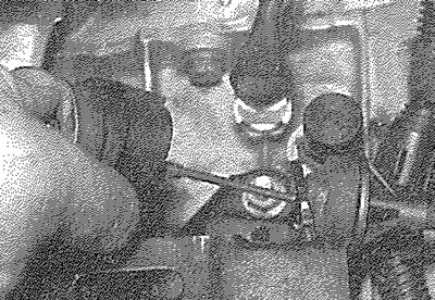
8.6. Free the clutch cable from the release lever and place it clear of the transmission
7. Disconnect the wiring connectors from the reversing light switch, TDC sensor and speedometer drive housing (as applicable). Undo the retaining nut and disconnect the earth straps from the top of the transmission housing (see illustration). Free the wiring from any relevant retaining clips and place it clear of the transmission.
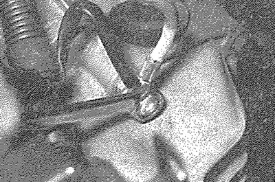
8.7. Undo the retaining nut and release the earth straps from the top of the transmission housing
8. Using a flat-bladed screwdriver, carefully lever the three gearchange mechanism link rods off their respective balljoints on the transmission. Position the rods clear of the transmission unit.
9. Withdraw the rubber retaining pin and disconnect the speedometer cable from the drive housing, freeing it from any relevant retaining clips.
10. On cast-iron block engines, unbolt the flywheel cover plate from the base of the transmission and remove it from the vehicle.
11. Working as described in Chapter 8, free the inner end of each driveshaft from the transmission and position them clear of the transmission (see illustration). Note that there is no need to unscrew the driveshaft retaining nuts; each driveshaft can be left secured to the hub. Support the driveshafts, however, to avoid placing any strain on the driveshaft joints or gaiters.
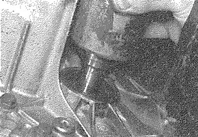
8.11. Disconnect the driveshafts from the transmission, noting that it is not necessary to disconnect them from the hubs
12. Place a jack with interposed block of wood beneath the engine, to take the weight of the engine. Alternatively, attach a hoist or support bar to the engine lifting eyes and take the weight of the engine (see illustration).
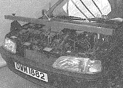
8.12. Take the weight of the engine with an engine support bar...
13. Place a trolley jack and block of wood beneath the transmission and raise the jack to take the weight of the transmission (see illustration).
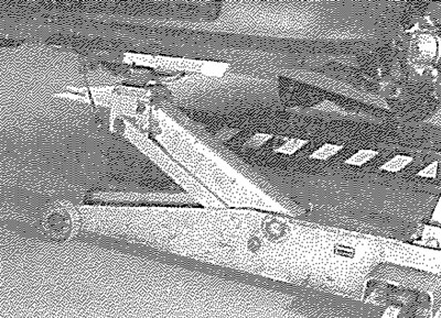
8.13. ... and position a jack with interposed block of wood underneath the transmission
14. Slacken and remove the centre nut and washer from the left-hand engine/transmission mounting. Undo the two bolts securing the mounting bracket assembly to the vehicle body, then remove the mounting bracket assembly. Recover the spacer from the stud.
15. Slacken and remove the two bolts securing the rear engine mounting to the transmission. Unscrew the nut and bolt securing the mounting link to the vehicle body and remove the mounting assembly from the vehicle (see illustrations).
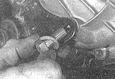
8.15a. Unscrew the two bolts securing the rear mounting to the transmission...
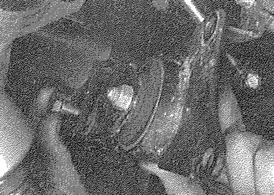
8.15b.... then undo the bolt securing the mounting link to the body and remove the mounting assembly from the vehicle
16. With the jack beneath the transmission taking its weight, slacken and remove the remaining bolts securing the transmission housing to the engine. Note the correct fitted positions of each boit and the necessary brackets, as they are removed, to use as a reference on refitting. On diesel models, it may be necessary to remove the fuel filter to gain access to the upper transmission-to-engine unit bolts (see Chapter 1B); if the filter is damaged on removal, a new one must be used on refitting.
17. Make a final check that all necessary components have been disconnected and are positioned clear of the transmission so that they will not hinder the removal procedure.
18. With the bolts removed, move the trolley jack and transmission to the left to free it from its locating dowels.
19. Once the transmission is free, lower the jack and manoeuvre the unit out from under the car (see illustration). If they are loose, remove the locating dowels from the transmission or engine and keep them in a safe place.
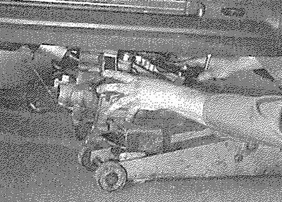
8.19. Carefully release the transmission from the engine and lower it out of position
Refitting
20. The transmission is refitted using a reversal of the removal procedure, bearing in mind the following points:
- a) Apply a little high-melting point grease to the splines of the transmission input shaft. Do not apply too much, otherwise there is a possibility of the grease contaminating the clutch friction plate.
- b) Ensure that the locating dowels are correctly positioned prior to installation.
- c) Tighten all nuts and bolts to the specified torque (where given).
- d) Renew the driveshaft oil seals using the information given in Section 5.
- e) On completion, refill the transmission with the specified type and quantity of oil as described in Section 2.