



Table of contents: Removal 🠇 All except right-hand driveshaft…🠇 Right-hand driveshaft with…🠇 Refitting 🠇 All except right-hand driveshaft…🠇 Right-hand driveshaft with…🠇
Note: A balljoint separator tool will be required for this operation. A new driveshaft nut, a new track-rod end-to-steering arm nut and a new hub carrier-to-lower arm balljoint clamp nut, must be used on refitting.
Removal
1. Chock the rear wheels then jack up the front of the vehicle and support it on axle stands (see "Jacking and vehicle support"). Remove the appropriate front roadwheel.
2. Drain the transmission oii/fluid as described in Chapter 7A (manual transmission) or Chapter 1A (automatic transmission).
3. Where applicable, to avoid any possibility of damage during the following procedure, remove the ABS wheel sensor from the hub carrier as described in Chapter 9.
4. Using a hammer and a suitable cold chisel or punch, relieve the staking on the driveshaft nut (see illustration).
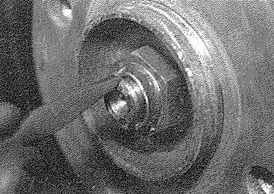
2.4. Relieving the staking on the driveshaft nut
Warning: Wear suitable eye protection.
5. The front hub must now be held stationary in order to loosen the driveshaft nut. Ideally, the hub should be held by a suitable tool bolted into place using two of the wheel bolts (see illustration). Alternatively, refit at least two wheel bolts, tighten them securely, then have an assistant firmly apply the brake pedal to prevent the hub from rotating. Using a socket and extension bar, slacken and remove the driveshaft nut.
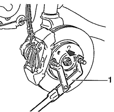
2.5. Using a suitable tool (1) to hold the front hub whilst loosening the driveshaft nut (arrowed)
Warning: Take care that the vehicle is adequately supported, as the nut is very tight! Discard the nut - a new one must be used on refitting.
6. If removing the left-hand driveshaft on automatic transmission models, unscrew the three bolts securing the driveshaft gaiter retaining plate to the transmission casing.
7. On models where the anti-roll bar is connected to the suspension strut body, undo the nut and washer securing the drop link to the strut and position the link clear of the strut. On models where the anti-roll bar is connected directly to the lower arm, remove the two screws and washers securing the anti-roll bar end clamp to the lower arm. Remove the clamp and the rubber bush.
8. Partially unscrew the nut securing the track-rod end to the steering arm on the suspension strut. Using a balljoint separator tool, separate the track-rod end from the steering arm. Remove the nut and washer (see illustrations).
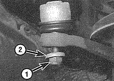
2.8a. Unscrew the nut (1). Note the washer (2)
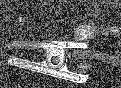
2.8b. Using a balljoint separator tool to separate the track-rod end from the steering arm
9. Undo the nut (while counterhoiding the bolt) and withdraw the hub carrier-to-lower arm clamp bolt, noting which way round it is fitted (see illustrations).
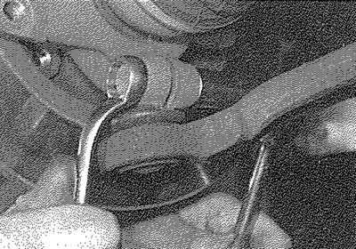
2.9a. Undo the nut, while counterholding the bolt...
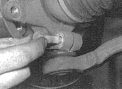
2.9b.... and withdraw the bolt Note that the bolt fits from the front of the strut
10. Using a suitable metal bar, lever the lower arm downwards just enough to release the balljoint shank from the lower arm. If the balljoint is a tight fit in the hub carrier, use a large flat-bladed screwdriver to carefully open up the clamp a little. Recover the balljoint rubber gaiter protector if it is loose.
11. Release the hub from the driveshaft splines by pulling the strut/hub carrier assembly outwards (see illustration). If necessary, the shaft can be tapped out of the hub using a soft-faced mallet. Support the driveshaft with a piece of string or wire - do not allow the end of the driveshaft to hang down, or the joint may be damaged.
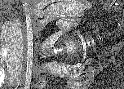
2.11. Releasing the driveshaft from the hub
All except right-hand driveshaft with intermediate bearing
12. Support the driveshaft, then withdraw the inner constant velocity joint from the transmission, taking care not to damage the driveshaft oil seal (see illustration). If removing the left-hand driveshaft on automatic transmission models, take care not to allow the inner joint rollers to drop off the tripod as the joint is withdrawn from the transmission. Remove the driveshaft from the vehicle.
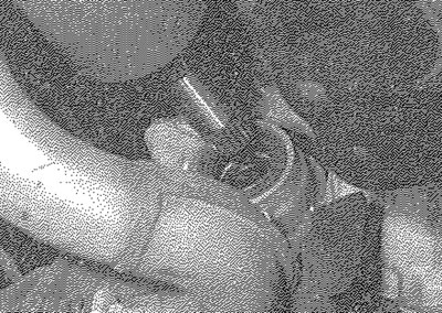
2.12. Withdraw the driveshaft from the transmission
Right-hand driveshaft with intermediate bearing
13. Loosen the two intermediate bearing retaining bolt nuts, then rotate the bolts through 90°, so that their offset heads are clear of the bearing outer race.
14. Support the outer end of the driveshaft, then pull on the inner end of the shaft to free the intermediate bearing from its mounting bracket.
15. Once the driveshaft end is free from the transmission, slide the dust seal off the inner end of the shaft, noting which way around it is fitted and remove the driveshaft from the vehicle.
Refitting
16. Before installing the driveshaft, examine the driveshaft oil seal in the transmission for signs of damage or deterioration and, if necessary, renew it, referring to Chapter 7A or 7B for further information (it is advisable to renew the seal as a matter of course).
17. Thoroughly clean the driveshaft splines and the apertures in the transmission and hub assembly. Apply a thin film of grease to the oil seal lips and to the driveshaft splines and shoulders. Check that all driveshaft gaiter clips are securely fastened.
All except right-hand driveshaft with intermediate bearing
18. Offer up the driveshaft and engage the joint splines or the tripod rollers with the differential sun gear, taking great care not to damage the oil seal. Push the joint fully into position. Support the driveshaft until both ends have been refitted.
19. Ensure that the driveshaft splines and the corresponding splines in the hub are clean, then engage the driveshaft with the hub. Fit a new driveshaft nut, tightening it by hand only at this stage.
20. Ensure that the protector plate is in place over the lower arm balljoint, then engage the balljoint taper with the hub carrier (see illustration). If necessary, lever the arm downwards just enough to engage the balljoint, as during removal. Similarly, use a screwdriver to open up the clamp a little if necessary.
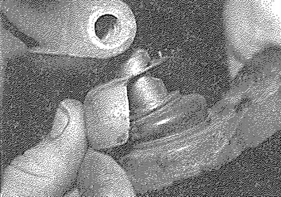
2.20. Ensure that the balljoint protector plate is in place
21. Fit the hub carrier-to-lower arm clamp bolt (inserting the bolt from the front of the strut) and a new nut and tighten to the specified torque.
22. Reconnect the track-rod end to the steering arm and fit the washer and a new nut. Tighten the nut to the specified torque.
23. Reconnect the anti-roll bar to the lower arm, or the anti-roll bar drop link to the strut, as applicable. Ensure that the washers are in place, then tighten the fixings to the specified torque.
24. Grease the driveshaft nut contact face on the hub bearing and the threads of the driveshaft nut, then hold the hub stationary as during removal and tighten the new driveshaft nut to the specified torque. Stake the nut into position.
25. If the left-hand driveshaft on automatic transmission models is being refitted, locate the driveshaft gaiter retaining plate on the transmission casing and secure with the three bolts.
26. Where applicable, refit the ABS wheel sensor, then refit the roadwheel and lower the vehicle to the ground.
27. Refill the transmission with oil or fluid as described in Chapter 7A or 1A as applicable.
Right-hand driveshaft with intermediate bearing
28. Check that the intermediate bearing rotates smoothly, without any sign of roughness or undue free play between its inner and outer races. If necessary, renew the bearing as described in Section 5. Examine the dust seal for signs of damage or deterioration and renew if necessary.
29. Apply a smear of grease to the outer race of the intermediate bearing and to the inner lip of the dust seal.
30. Pass the inner end of the shaft through the bearing mounting bracket, then carefully slide the dust seal into position on the driveshaft, ensuring that its flat surface is facing the transmission (see illustration).
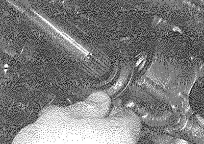
2.30. Slide the dust seal into position
31. Carefully engage the inner driveshaft splines with those of the differential sun gear, taking care not to damage the oil seal. Align the intermediate bearing with its mounting bracket and push the driveshaft fully into position. If necessary, use a soft-faced mallet to tap the outer race of the bearing into position in the mounting bracket. Support the driveshaft until it is completely refitted.
32. Ensure that the driveshaft splines and the corresponding splines in the hub are clean, then engage the driveshaft with the hub. Fit a new driveshaft nut, tightening it by hand only at this stage.
33. Ensure that the intermediate bearing is correctly seated, then rotate its retaining bolts back through 90°, so that their offset heads are resting against the bearing outer race. Tighten the retaining nuts to the specified torque. Ensure that the dust seal is tight against the driveshaft oil seal (see illustration).
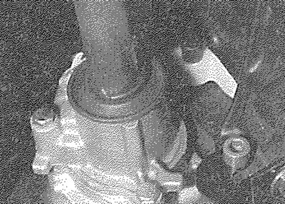
2.33. Ensure that the dust seal is tight against the driveshaft oil seal
34. Carry out the operations described previously in paragraphs 20 to 27 (with the exception of paragraph 25).