



Modulator assembly
Note: Before starting work, refer to the warning at the beginning of Section 2 concerning the dangers of hydraulic fluid.
Removal
1. Disconnect the battery negative terminal (refer to "Disconnecting the battery").
2. Remove the master cylinder as described in Section 13.
3. Remove the brake servo as described in Section 16.
4. Mark the locations of the hydraulic fluid pipes to ensure correct refitting, then unscrew the union nuts and disconnect the pipes from the modulator assembly. Be prepared for fluid spillage and plug the open ends of the pipes and the modulator, to prevent dirt ingress and further fluid loss. Note the position of the clip on the brake pipes to ensure correct refitting.
5. Disconnect the wiring connectors from the modulator assembly.
6. Remove the upper securing nut from the modulator mounting bracket (see illustration).
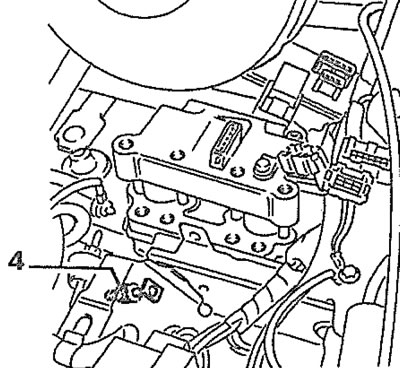
24.6. ABS modulator mounting bracket upper securing nut (4) (left-hand drive model shown)
7. Working under the modulator mounting bracket, unscrew the two lower mounting nuts, then withdraw the assembly, complete with the mounting bracket (see illustration).
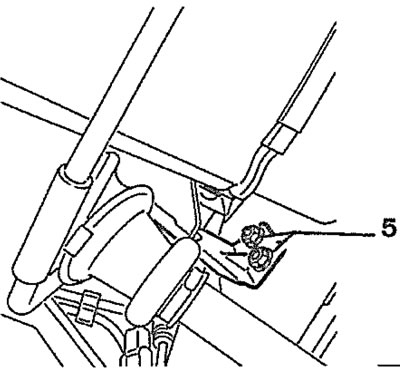
24.7. ABS modulator mounting bracket lower mounting nuts (5) (left-hand drive model shown)
Refitting
Warning: Do not reconnect the wiring connectors to the modulator until the hydraulic circuits have been bled as described in Section 2.
8. Commence refitting by positioning the assembly in the engine compartment and refitting the upper and lower securing nuts.
9. Reconnect the fluid pipes to the assembly, as noted before removal, ensuring that no dirt enters the system. Ensure that the brake pipe clip is fitted as noted before removal (see illustration).
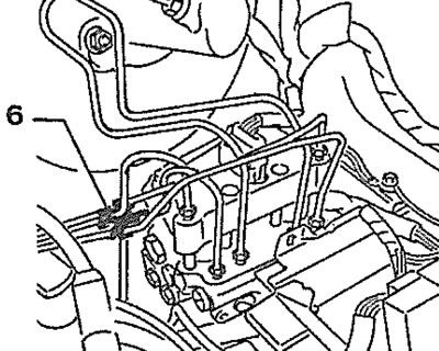
24.9. ABS hydraulic modulator fluid pipe clip (6)
10. Refit the brake servo as described in Section 16.
11. Refit the master cylinder as described in Section 13.
12. Bleed the complete hydraulic system as described in Section 2.
13. Reconnect the modulator assembly wiring plugs.
14. Reconnect the battery negative terminal.
Electronic control unit
Removal
15. The unit is mounted on a bracket on the left-hand side of the engine compartment, next to the battery (see illustration).
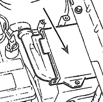
24.15. ABS electronic control unit location
16. Disconnect the battery negative terminal (refer to "Disconnecting the battery").
17. Release the securing clips and withdraw the cover from the control unit.
18. Release the securing clip and/or remove the securing screw, as applicable and disconnect the control unit wiring plug.
19. Unscrew the securing nuts and withdraw the control unit from the mounting bracket.
Refitting
20. Refitting is a reversal of removal.
Wheel sensor
Note: Suitable thread-locking compound must be applied to the sensor securing stud on refitting.
Removal
21. Disconnect the battery negative terminal (refer to "Disconnecting the battery").
22. Chock the rear wheels then jack up the front of the vehicle and support it on axle stands (see "Jacking and vehicle support"). If desired, remove the appropriate front roadwheel to improve access.
23. Follow the wiring back from the sensor and separate the two halves of the wiring connector. Release the wiring from the securing clips, noting its routing.
24. Unscrew the securing nut and withdraw the shield from the sensor (see illustration).
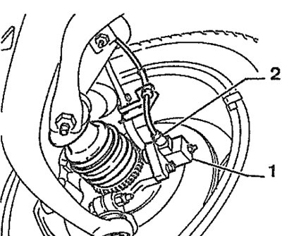
24.24. ABS wheel sensor shield (1) and sensor (2)
25. Unscrew the securing stud and withdraw the sensor from its mounting bracket.
Refitting
26. Refitting is a reversal of removal, bearing in mind the following points:
- a) Ensure that the mating faces of the sensor and the mounting bracket are clean and apply a little grease to the mounting bracket bore before refitting.
- b) Ensure that the end face of the sensor is dean (see illustration).
- c) Apply thread-locking compound the threads of the sensor securing stud and tighten to the specified torque.
- d) Ensure that the sensor wiring is routed as noted before removal.
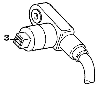
24.26. Ensure that the end face (3) of the sensor is clean