



Table of contents: Conventional braking system - rear…🠇 Conventional braking system -rear…🠇 Anti-lock braking system (ABS) 🠇
Conventional braking system - rear drum brakes
1. On models with a conventional braking system, the pressure-regulating valves are integral with the rear wheel cylinders. The cylinders must not be dismantled and if a fault is suspected, the complete wheel cylinder must be renewed as described in Section 12.
Conventional braking system -rear disc brakes
Removal
Note: Before starting work, refer to the warning at the beginning of Section 2 concerning the dangers of hydraulic fluid.
2. The pressure-regulating valves are located just in front of the rear axle assembly; there are two valves, one for each rear brake caliper.
3. Firmly chock the front wheels, then jack up the rear of the vehicle and support it on axle stands (see "Jacking and vehicle support").
4. Minimise fluid loss by first removing the master cylinder reservoir cap, and then tightening it down onto a piece of polythene, to obtain an airtight seal.
5. Wipe clean the area around the brake pipe unions on the relevant valve, and place absorbent rags beneath the pipe unions to catch any surplus fluid. Retain the relevant pressure-regulating valve with a suitable open-ended spanner, then slacken the union nuts, disconnect both brake pipes, and remove the valve from underneath the vehicle. Plug or tape over the pipe ends and valve orifices, to minimise the loss of brake fluid, and to prevent the entry of dirt into the system. Wash off any spilt fluid immediately with cold water.
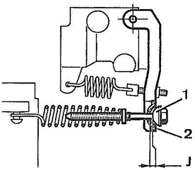
20.5. Rear brake pressure-regulating valve - ABS model 1. Bolt; 2. Lever; J = 1.0±0.5 mm;
Refitting
6. Refitting is a reverse of the removal procedure, ensuring that the pipe union nuts are securely tightened. On completion, bleed the complete braking system (see Section 2).
Anti-lock braking system (ABS)
Adjustment
7. On models with ABS, a load-sensitive pressure-regulating valve is fitted, which is connected to the rear axle assembly to sense the load on the rear of the vehicle.
8. To carry out a complete check on the valve, pressure-testing equipment must be used, but a simple check on the condition of the valve spring can be made as follows.
9. The check must be made with a ride height of 210 mm, measured from the rear jacking point cut-out to the ground. If necessary, ballast the rear of the vehicle to give the required ride height.
10. With the ride height correctly set, refer to the accompanying illustration and measure the clearance between the end face of the bolt (1) and the lever (2) (see illustration).
11. If the clearance is not as specified, adjust by turning the bolt (1) until the correct clearance is obtained.
Removal
12. To remove the valve, simply unhook the spring, then remove the two screws securing the assembly to the rear suspension.
Refitting
13. Refitting is a reversal of removal, but on completion, check the valve adjustment as described previously in this Section.