



Table of contents: Right-hand-drive models 🠇 Left-hand-drive models 🠇
Right-hand-drive models
Testing
1. To test the operation of the servo unit, with the engine switched off, depress the footbrake several times to exhaust the vacuum. Keep the pedal firmly depressed and start the engine. As the engine starts, there should be a noticeable "give" in the brake pedal as the vacuum builds up. Allow the engine to run for at least two minutes, then switch it off. If the brake pedal is now depressed, it should feel normal, but further applications should result in the pedal feeling firmer, with the pedal stroke decreasing on each application.
2. If the servo does not operate as described, first inspect the servo unit check valve as described in Section 17. On diesel models, also check the operation of the vacuum pump, as described in Section 26.
3. If the servo unit still fails to operate satisfactorily, the fault lies within the unit itself. Repairs to the unit are not possible - if faulty, the servo unit must be renewed.
Removal
Note: A new spring clip must be fitted to the servo pushrod clevis pin on refitting.
4. To improve access, remove the battery as described in Chapter 5A.
5. Unclip any relevant hoses and/or wiring from the fusebox bracket in front of the servo, then remove the nut securing the bracket to the wheel arch and move the bracket clear of the working area.
6. Where applicable, remove the air cleaner assembly as described in the relevant Part of Chapter 4.
7. On diesel models, remove the inlet manifold as described in Chapter 4D.
8. Carefully pull the non-return valve from the servo, leaving the vacuum hose connected (see illustration).
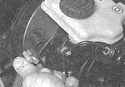
16.8. Pulling the non-return valve from the brake servo
9. Working under the servo, unclip the master cylinder brake fluid pipes from the supporting brackets.
10. Unscrew the two master cylinder securing nuts and detach the master cylinder from the servo. Where applicable, recover the seal (see illustrations).
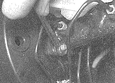
16.10a. Unscrew the securing nuts...
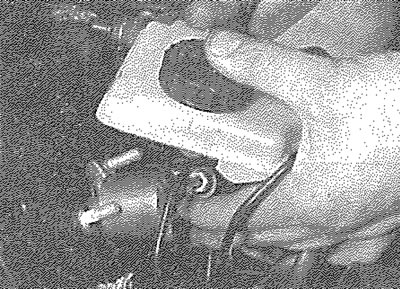
16.10b.... and detach the master cylinder from the servo
11. Carefully pull the master cylinder forwards from the servo, taking care not to strain the fluid pipes.
12. Unclip the plastic cover from the pedal end of the linkage, then slacken the link rod end nut sufficiently to disconnect the link rod end fitting from the pedal relay lever. Do not move the inner nut on the link rod (this should be left in position, to preserve the link rod adjustment) (see illustration).
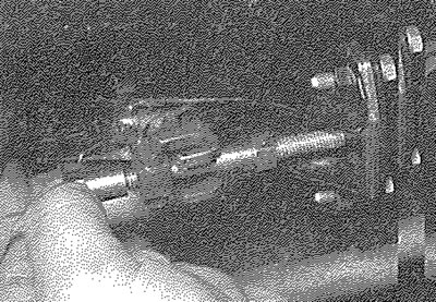
16.12. Slacken the link rod end nut
13. Remove the linkage crosstube securing bolts (two at each end of the tube) and remove the spacer plate from the pedal end of the crosstube (see illustrations).
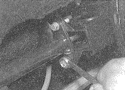
16.13a. Unscrewing a linkage crosstube securing bolt
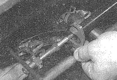
16.13b. Removing the spacer plate from the crosstube
14. Slide the link rod end fitting from the pedal relay lever.
15. Unscrew the four nuts securing the servo mounting bracket to the bulkhead, then carefully manipulate the servo and crossover linkage assembly from the engine compartment, taking care not to strain the master cylinder brake pipes (see illustrations).
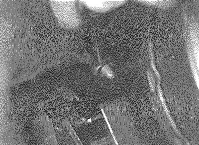
16.15a. Unscrewing a servo mounting bracket securing nut
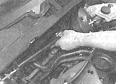
16.15b. Removing the servo and crossover linkage assembly
16. Prise off the spring clip and withdraw the clevis pin securing the servo pushrod to the crossover linkage.
17. Unscrew the four securing nuts and withdraw the servo from the mounting bracket.
Refitting
18. Refitting is a reversal of removal, bearing in mind the following points:
- a) Tighten all fixings to the specified torque (where given).
- b) Where applicable, refit the inlet manifold as described in Chapter 4D.
- c) Where applicable, refit the servo-end linkage and the main crossover linkage.
Left-hand-drive models
Testing
19. Proceed as described in paragraphs 1 to 3 inclusive.
Removal
Note: A new spring clip must be fitted to the servo pushrod clevis pin on refitting.
20. Proceed as described in paragraphs 4 to 10 inclusive, then proceed as follows.
21. Working inside the vehicle, unclip the front edge of the under-facia trim panel from the facia and lower the panel. Unscrew the two nuts securing the trim panel to the studs in the footwell, then withdraw the panel from the footwell.
22. Working in the footwell, unscrew the securing nut from the lower column pinchbolt, then carefuily tap the pinch-bolt from the universal joint. Pull off the metal clip securing the column to the steering gear pinion (see Chapter 10, Section 12, paragraph 5)
23. Make alignment marks on the universal joint and the steering gear pinion, then push the universal joint upwards to separate it from the pinion. Manipulate the lower steering column as necessary for access to the brake pedal assembly.
24. Remove the spring clip from the end of the brake servo pushrod-to-brake pedal clevis pin, then withdraw the clevis pin.
25. Working in the engine compartment, remove the four securing nuts from the studs at the rear of the servo, then remove the servo from its mounting bracket.
Refitting
26. Refit the servo to its mounting bracket and tighten the securing nuts.
27. Reconnect the servo pushrod to the pedal and fit the clevis pin. Secure the clevis pin with a new spring clip.
28. Slide the column universal joint over steering gear pinion, ensuring that the marks made before removal are still aligned then refit the metal clips.
29. Fit a new lower column pinch-bolt and nut, ensuring that the lugs on the bolt engage with the cut-outs in the universal joint and tighten the nut to the specified torque (see Chapter 10 Specifications).
30. Refit the under-facia trim panel.
31. Further refitting is a reversal of removal, but tighten all fixings to the specified torque. On diesel models, refit the inlet manifold as described in Chapter 4D.