



Adjustment
1. With the brake pedal at rest, adjust the position of the stop-light switch in its mounting bracket to obtain the clearance shown between the end of the switch plunger and the stop on the brake pedal (see illustration). On some models, the switch is screwed into the mounting bracket and a locknut must be loosened before the switch can be moved (it will also be necessary to disconnect the wiring before the switch is rotated).
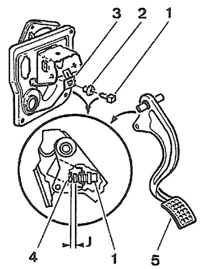
21.1. Stop-light switch adjustment (left-hand-drive model shown) 1. Stop-light switch; 2. Mounting clip; 3. Pedal bracket; 4. Stop on brake pedal; 5. Brake pedal; J = 2.0 to 3.0 mm
[Information copied from the resource: PeugeotBook.ru]
2. The switch must operate the stop-lights when the pedal has travelled a maximum of 5.0 mm.
Removal
3. Disconnect the battery negative terminal (refer to "Disconnecting the battery").
4. Working in the driver's footwell, unclip the front edge of the under-facia trim panel from the facia and lower the panel. Unscrew the two nuts securing the trim panel to the studs in the footwell, then withdraw the panel from the footwell.
5. Reach up and disconnect the wiring from the switch.
6. Where applicable, release the securing clip and pull the switch from the pedal bracket assembly. Alternatively, where the switch is screwed into position, loosen the locknut and unscrew the switch from the bracket (see illustration).
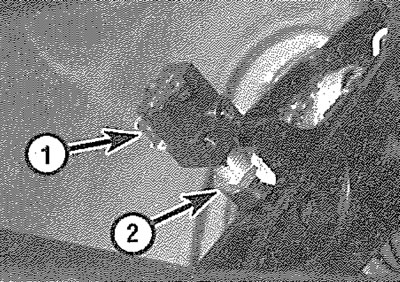
21.6. Stop-light switch (1) and locknut (2) -right-hand-drive model viewed with facia removed
Refitting
7. Refitting is a reversal of removal. On completion, check the adjustment of the switch as described previously in this Section.