



Table of contents: Manual transmission models 🠇 Automatic transmission models 🠇
Manual transmission models
Outer joint
1. Remove the driveshaft as described in Section 2.
2. Remove the inner constant velocity joint and gaiter as described in paragraphs 13 to 20. It is recommended that the inner gaiter is also renewed, regardless of its apparent condition.
3. Release the two outer gaiter retaining clips, then slide the gaiter off the inner end of the driveshaft.
4. Thoroughly clean the outer constant velocity joint using paraffin, or a suitable solvent and dry it thoroughly. Carry out a visual inspection of the joint.
[Source of the article is website: PeugeotBook.ru]
5. Check the driveshaft spider and outer member yoke for signs of wear, pitting or scuffing on their bearing surfaces. Also check that the outer member pivots smoothly and easily, with no traces of roughness.
6. If on inspection, the spider or outer member reveal signs of wear or damage, it will be necessary to renew the complete driveshaft as an assembly, since no components are available separately. If the joint components are in satisfactory condition, obtain a repair kit from your Peugeot dealer, consisting of a new gaiter, retaining clips and the correct type and quantity of grease (see illustration).
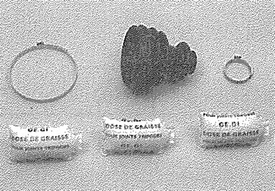
3.6. Driveshaft outer joint gaiter repair kit components
7. Tape over the splines on the inner end of the driveshaft, then carefully slide the outer gaiter onto the shaft (see illustration).
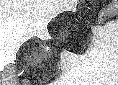
3.7. Sliding the outer joint gaiter onto the driveshaft
8. Pack the joint with the grease supplied In the repair kit (see illustration). Work the grease well into the bearing tracks whilst twisting the joint and fill the rubber gaiter with any excess.
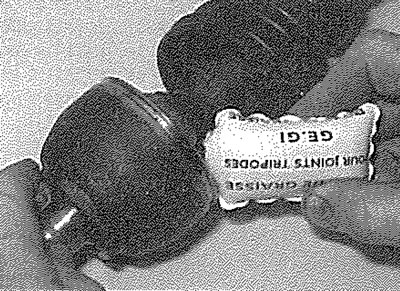
3.8. Pack the joint with the grease supplied in the repair kit
9. Ease the gaiter over the joint and ensure that the gaiter lips are correctly located in the grooves on both the driveshaft and constant velocity joint. Lift the outer sealing lip of the gaiter, to equalise air pressure within the gaiter.
10. Fit the large metal retaining clip to the gaiter. Remove any slack in the gaiter retaining clip by carefully compressing the raised section of the clip, in the absence of the special tool, a pair of side cutters may be used. Secure the small retaining clip using the same procedure (see illustration). Check that the constant velocity joint moves freely in all directions before proceeding further.
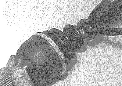
3.10. Securing a gaiter securing clip using side cutters
11. Refit the inner constant velocity joint as described in paragraphs 21 to 28.
Inner joint
12. Remove the driveshaft as described in Section 2.
13. Secure the driveshaft in a vice equipped with soft jaws then, using a suitable pair of pliers, carefully peel back the lip of the constant velocity joint outer member cover (see illustration).
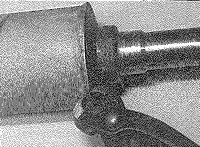
3.13. Peeling back the lip of the joint outer member cover
14. Once the lip of the cover is fully released, pull.the joint outer member out from the cover and recover the spring and thrust cap from the end of the shaft. Remove the O-ring from the outside of the outer member and discard it.
15. Fold the gaiter back and wipe away the excess grease from the tripod joint. If the rollers are not secured to the joint with circlips, wrap adhesive tape around the joint to hold them in position.
16. Using a dab of paint, or a hammer and punch, mark the relative position of the tripod joint in relation to the driveshaft. Using circlip pliers, extract the circlip securing the joint to the driveshaft (see illustration).
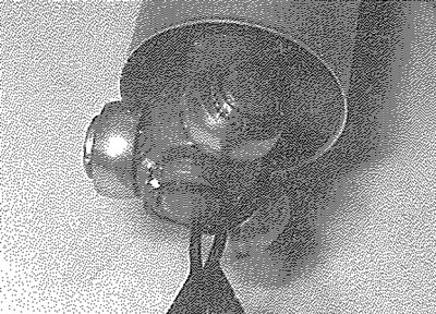
3.16. Removing the inner tripod joint securing circlip
17. The tripod joint can now be removed. If it is tight, draw the joint off the driveshaft end, using a two- or three-legged bearing puller. Ensure that the legs of the puller are located behind the joint inner member and do not contact the joint rollers (see illustrations). Alternatively, support the inner member of the tripod joint and press the shaft out of the joint using a hydraulic press, ensuring that no load is applied to the joint rollers.
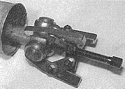
3.17a. Using a three-legged puller to remove the inner tripod joint
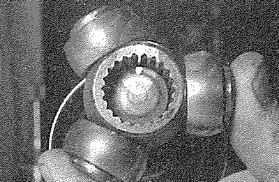
3.17b. Withdrawing the inner tripod joint. Note the alignment marks (made in the previous paragraph)
18. With the tripod joint removed, slide the gaiter and inner retaining collar off the end of the driveshaft.
19. Thoroughly clean the constant velocity joint components using paraffin, or a suitable solvent and dry them thoroughly - take great care not to remove the alignment marks made on dismantling, especially if paint was used. Carry out a visual inspection of the joint.
20. Examine the tripod joint, rollers and outer member for any signs of scoring or wear and for smoothness of movement of the rollers on the tripod stems. If any component is worn, the complete driveshaft assembly must be renewed; no joint components are available separately. If the joint components are in good condition, obtain a repair kit from your Peugeot dealer, consisting of a new rubber gaiter and outer cover assembly, circlip, thrust cap, spring, O-ring and the correct quantity of the special grease (see illustration).
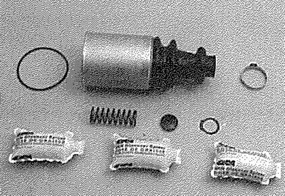
3.20. Driveshaft inner joint gaiter repair kit components
21. Tape over the splines on the end of the driveshaft and carefully slide the inner retaining collar and gaiter/cover assembly onto the shaft (see illustrations).
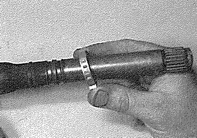
3.21a. Slide on the inner retaining collar...
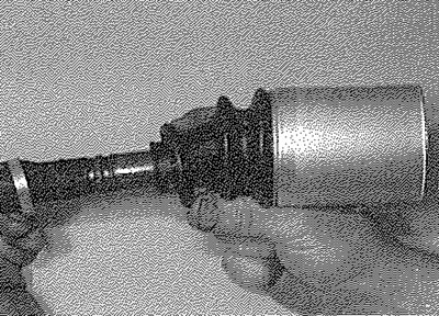
3.21b.... and the gaiter/cover assembly
22. Remove the tape then, aligning the marks made on dismantling, engage the tripod joint with the driveshaft splines. Use a hammer and soft metal drift (or a suitable tube or socket) to tap the joint onto the shaft, taking great care not to damage the driveshaft splines or joint rollers (see illustration).
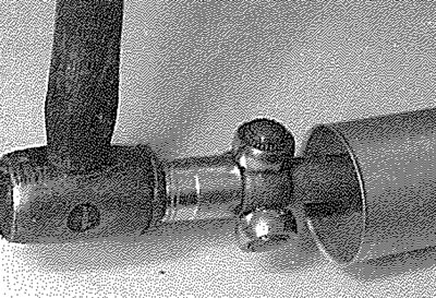
3.22. Using a hammer and a socket to tap the joint onto the driveshaft
23. Secure the tripod joint in position with the new circlip, ensuring that it is correctly located in the driveshaft groove.
24. Remove the tape and evenly distribute the special grease contained in the repair kit around the tripod joint and outer member (see illustration). Pack the gaiter/cover with more grease, then draw the cover over the tripod joint Leave one sachet of grease to lubricate the outer member as the joint is fitted.
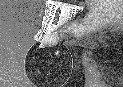
3.24. Pack the joint and gaiter/cover with grease
25. Fit the new spring, thrust cap and O-ring to the joint outer member (see illustrations).
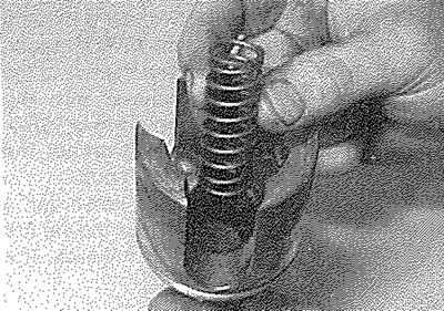
3.25a. Fit the new spring...
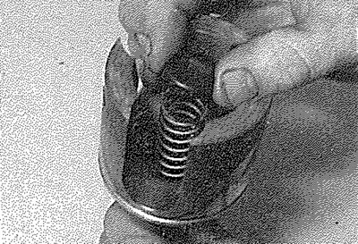
3.25b.... thrust cap...
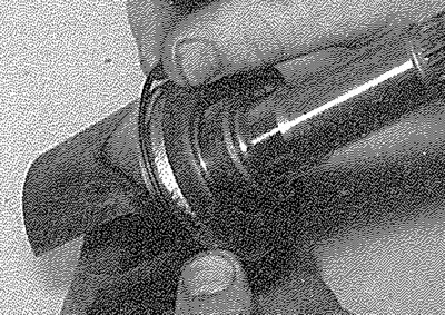
3.25c.... and O-ring
26. Position the outer member assembly over the tripod joint and locate the thrust cap against the end of the driveshaft. Apply the remainder of the grease to the joint, then push the outer member onto the shaft, compressing the spring and locate it inside the outer cover. Secure the outer member in position by peening the end of the cover evenly over the joint outer edge (see illustrations).
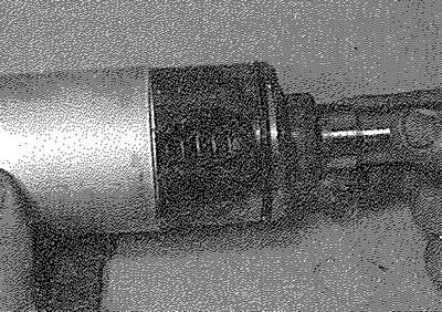
3.26a. Position the outer member over the tripod joint...
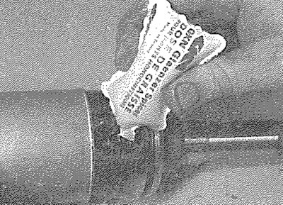
3.26b.... then apply the remainder of the grease...
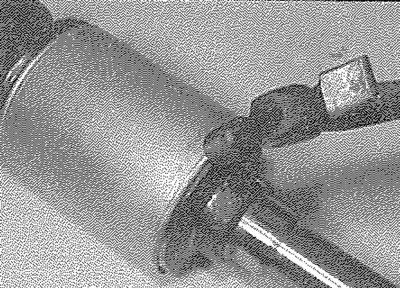
3.26c.... and peen over the end of the cover
27. Briefly lift the inner gaiter lip, using a blunt instrument such as a knitting needle, to equalise the air pressure within the gaiter. Secure the inner clip in position (see illustration).
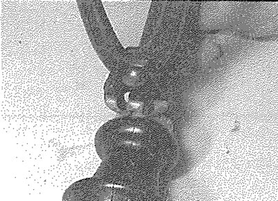
3.27. Securing the inner gaiter clip in position
28. Check that the constant velocity joint moves freely in all directions, then refit the driveshaft to the vehicle as described in Section 2.
Automatic transmission models
29. The procedure for renewal of the inner and outer joint gaiters on the right-hand driveshaft is as described previously for manual transmission models.
30. At the time of writing no information was available for the renewal of the left-hand driveshaft inner joint gaiter on these models. If inner or outer joint gaiter renewal is necessary, the driveshaft should be removed from the vehicle and taken to a Peugeot dealer.