



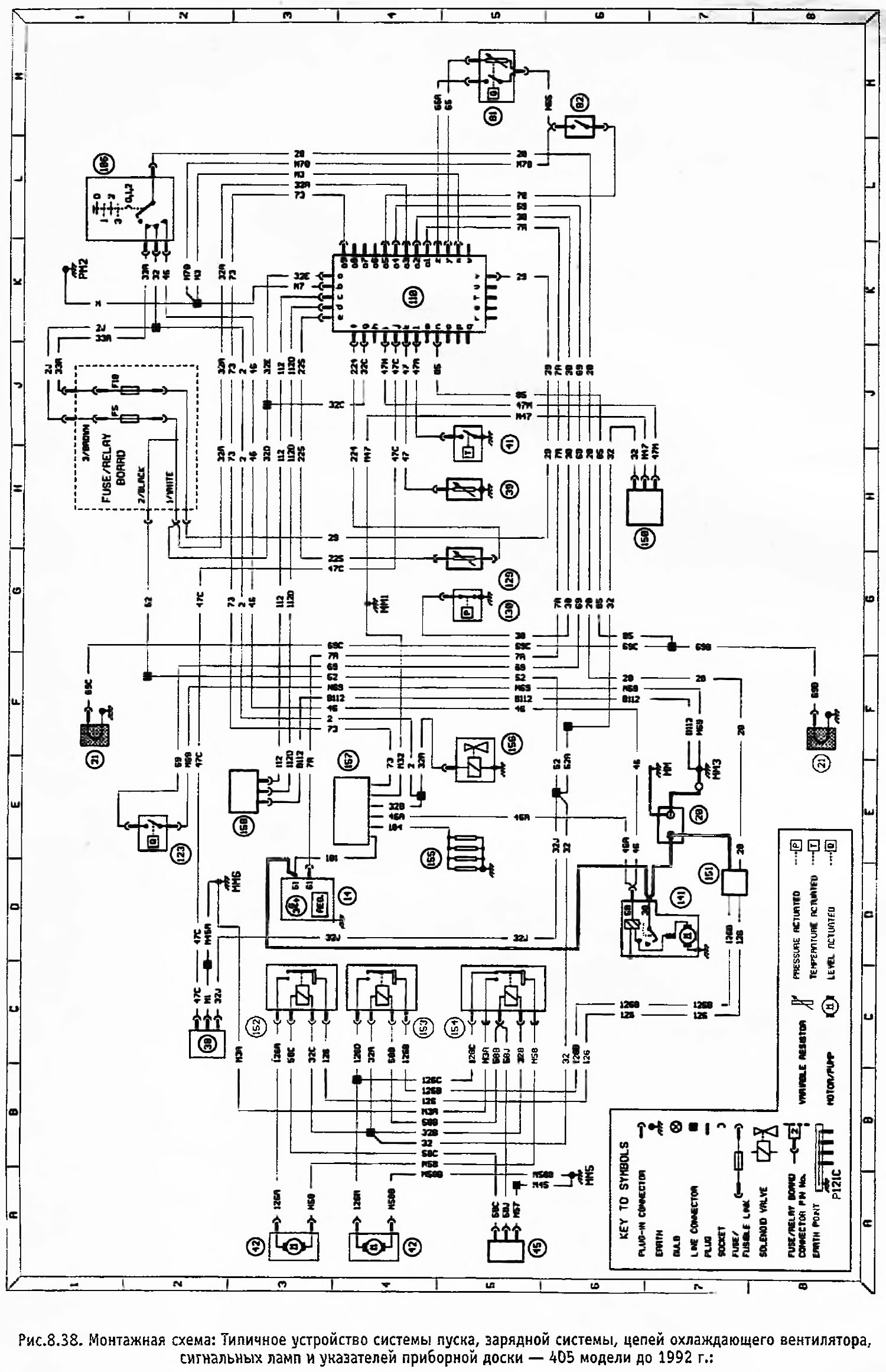
Figure 8.38. Wiring Diagram: Typical Layout of Starting System, Charging System, Cooling Fan Circuits, Instrument Cluster Indicators and Signal Lamps - 405 Models Pre-1992.
Open a larger image in a new tab »
Conventional designations
- 14 Generator
- 20 Battery
- 21 Brake pad wear sensor
- 38 Coolant level indicator
- 39 Coolant temperature sensor
- 41 Cooling system thermal switch
- 42 Electric motor of the cooling fan
- 45 Cooling fan switch
- 81 Fuel level sensor
- 92 Handbrake warning light switch
- 106 Ignition switch
- 110 Instrument cluster
- 123 Low brake fluid level sensor
- 129 Oil level sensor
- 130 Oil pressure relay
- 141 Starter
- 150 Switch (water in fuel)
- 151 Control unit (serving of the litany)
- 152 Cooling Fan Relay
- 153 Relay "A" of the cooling fan
- 154 Relay "B" of the cooling fan
- 155 Glow Plugs
- 156 Pump shut-off solenoid
- 157 Pre-heater control unit
- 158 TDC sensor
Legend for the instrument cluster (position 110)
- and Power supply +VE
- b "Earth"
- with Tachometer
- d Tachometer
- e Oil level indicator
- f Oil level indicator
- g Power supply +VE
- h Power supply +VE
- i Water in fuel warning light
- j Low coolant level warning light
- k Coolant temperature gauge
- l High coolant temperature warning light
- m Power supply +VE
- p Brake pad wear indicator light
- o Power supply +VE
- r ABS system warning light
- q Turn signal light
- r Parking light indicator lamp
- s Low beam indicator light
- t High beam indicator light
- u Hours
- v Power supply +VE
- w Turn signal light
- x "Earth"
- y Fuel level indicator
- z Low fuel level warning light
- a1 Low battery warning light
- a2 Low oil pressure warning light
- a3 Power supply +VE
- a4 Low brake fluid level warning light
- a5 Handbrake on indicator light
- a6 Instrument panel lighting
- a7 "Earth"
- a8 Oil temperature gauge
- a9 Pre-heater indicator lamp
Note: Wires are not marked by color, but by letters or numbers located at both ends of the wire.