



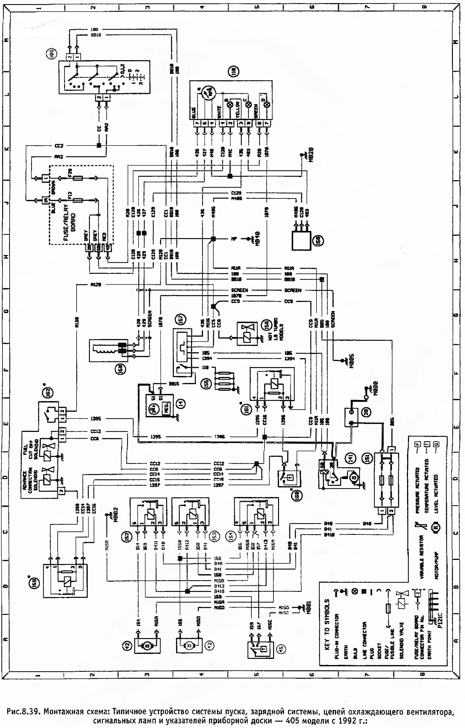
Figure 8.39. Wiring Diagram: Typical Arrangement of Starting System, Charging System, Cooling Fan Circuits, Instrument Cluster Indicator Lights and Gauges - 405 Models Since 1992.
Open a larger image in a new tab »
Conventional designations
- Generator
- Battery
- Cooling fan thermal switch
- Cooling fan switch
- Ignition switch
- Instrument cluster
- Switch (water in fuel)
- Control unit (power supply)
- Cooling Fan Relay "A"
- Cooling fan relay "B"
- Cooling fan relay "C"
- Glow plugs
- Pump shut-off solenoid
- Pre-heater control unit
- TDC sensor
Optional equipment found on turbocharged LS models only
- Injection advance corrector relay
- After-heater thermal switch
- After-heater relay
- Fuel injection pump
Legend for the instrument cluster (position 110)
- a Tachometer
- b Pre-heater indicator lamp
- d Water in fuel warning light
- e Low battery warning light
Note: Wires are not marked by color, but by letters or numbers located at both ends of the wire.