
- turn off the ignition and disconnect the wire «masses» from the storage battery;
- remove the air filter housing;
- remove the air intake pipe;
- remove the decorative battery cover;
- remove the battery;
- remove the battery support;
- disconnect, release from fasteners and take aside the wiring harnesses going to the gearbox;
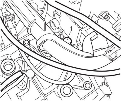
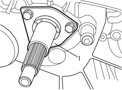
Pic. 5.10. Sensor location (1) engine speed
- remove sensor 1 (pic. 5.10) engine speed;
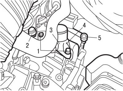
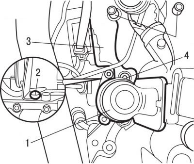
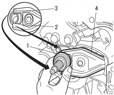
Pic. 5.11. Location of elements on the gearbox: 1 - bolts; 2 - transitional thrust; 3 - support for gear shift rods; 4 - jet rod; 5 - nut
- using the ball joint remover 0216-G1 with a diameter of 10 mm, disconnect the adapter rod 2 (pic. 5.11);
- using a tool for removing ball joints 0216-G2 with a diameter of 13 mm, disconnect the torque rod 4;
- Turn out bolts 1 and a nut 4 and remove a support 3 drafts of a gear change;
- remove the wiper arms;
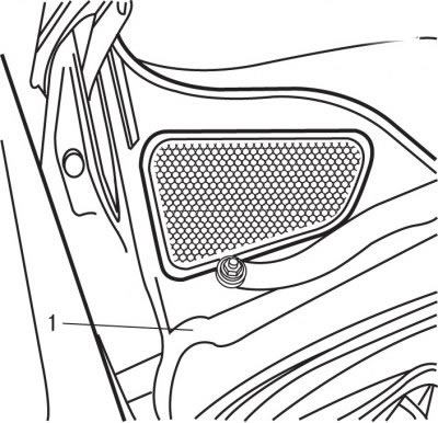
Pic. 5.12. Lattice location (1) panels in front of the windshield
- remove grate 1 (pic. 5.12) panels in front of the windshield;
- install a support cross member to support the power unit;
- hook the catch of the support cross member to the bracket to lift the engine;
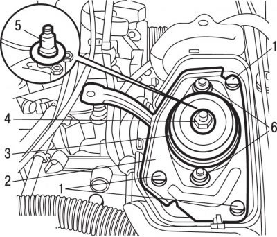
Pic. 5.13. Elastic support attachment: 1 - bolts; 2 - bracket; 3 - elastic support; 4 - nut, 65 Nm; 5 - gearbox axis; 6 - bolts, 30 Nm
- unscrew nut 4 (pic. 5.13) fasteners from the axis of the gearbox support and remove it together with the washer;
- turn out bolts 6 fastenings of a pillow;
- remove the elastic support 3;
- turn out bolts 1 and remove an arm 2 an axis of a transmission;
- using a special bushing 0317-AB, remove the gearbox suspension axle 5;
- raise the car by hanging the front wheels;
- remove the front wheels;
- remove the bottom protection of the engine compartment;
- remove the mudguard of the left front wheel arch;
- install a drip tray under the engine to collect leaked oil;
- drain the oil from the gearbox;
- remove the drive shafts;
- Disconnect the exhaust pipe. It is necessary to protect the connecting element in the front exhaust pipe from any mechanical damage;
Attention! The connector in the front exhaust pipe must not be bent by more than 20°in the angle of rotation or misaligned by 20 mm axially and 25 mm radially, otherwise it will be damaged.
Pic. 5.14. The location of the starter mounting elements: 1 - clutch slave cylinder; 2 - starter; 3 - wiring harness; 4 - mounting bolts
- remove bolts 4 (pic. 5.14), remove the clutch slave cylinder 1 and attach it to the body with a soft wire;
- unscrew the starter fastening bolts 2 and wiring harness supports 3;
- take the starter to the side without removing it;
Attention! Do not disconnect the hydraulic hose from the clutch slave cylinder and do not depress the clutch pedal.
- remove the jet engine mount bracket;
- remove the bump stop and shockproof amplifier of the sub-frame;
- use the threaded rod of the support cross member to lower the power unit slightly;
- hook the grips of the lifting cables to the gearbox;
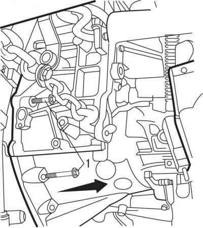
Pic. 5.15. Bolt location (1) top mount gearbox
- remove bolts 1 (pic. 5.15) top mount gearbox;
- protect the inside of the radiator of the cooling system with a sheet of cardboard cut to the size of the radiator;
- remove the gearbox;
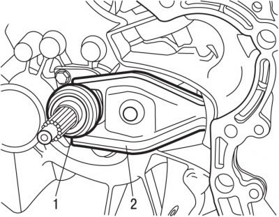
Pic. 5.16. Clutch release bearing location (1) and forks (2)
- if necessary, remove the clutch release bearing 1 (pic. 5.16) and fork 2.
To install the gearbox:
- check the condition of the clutch;
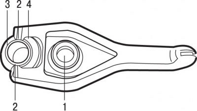
Pic. 5.17. Clutch release fork: 1 - clutch release bearing; 2 - ledges; 3 - fork tips; 4 - ball joint insert
- check the condition of the ball joint bushing 4 (pic. 5.17). If the condition of the ball bearing is not satisfactory, replace the clutch release fork;
- lubricate with a thin layer of special grease G12 sections 3 of the clutch release fork, on which the clutch release bearing is mounted;
- install the clutch release bearing 1 so that the protrusions 2 enter the tips of the fork 3;
- clean the splined part of the input shaft of the gearbox;
Pic. 5.18. Guide sleeve location (1) clutch release bearing
- lubricate the guide bush 1 with a thin layer of special grease G12 (pic. 5.18) clutch release bearing. The lubrication layer must be thin and uniform, otherwise, during clutch operation, excess lubricant will be thrown onto the working surfaces of the clutch, which can disrupt its operation;
Attention! Do not apply grease to the transmission input shaft splines.
Pic. 5.19. Clutch fork installation: 1 - clutch release bearing; 2 - ledges; 3 - tips; 4 - fork
- reinstall the fork with the clutch release bearing. Move the clutch release bearing 1 (pic. 5.19) until the protrusions 2 are installed in place of the tips 3 of the fork 4 of the clutch. Check that the clutch release bearing moves with the fork;
- replace the differential sealing rings, having previously lubricated the working edges of the rings;
- replace with new self-locking nuts and bolts, as well as lock washers and seals;
Attention! Make sure that guide bushings are installed in the engine block to center the gearbox.
- lifting, attach the gearbox to the engine;
- move the gearbox towards the engine so that the input shaft of the gearbox enters the splines of the clutch disc. It may be necessary to turn the engine crankshaft slightly to align the gearbox input shaft splines with the clutch driven plate splines. When installing the gearbox, the input shaft must not hang on the clutch disc;
- moving the gearbox forward, install the clutch housing on the guide bushings of the cylinder block;
- screw in the upper gearbox mounting bolts and tighten them to a torque of 55 Nm;
- clean the threads of the gearbox suspension axle from dirt and apply a thin layer of E3 grease to it;
- reinstall support 3 (see fig. 5.11) gearshift rods and connect the adapter rod 2 and torque rod 4. Tighten the nut 4 to 19 Nm, and the bolts 1 to 13 Nm;
- install the starter and secure it with bolts;
- Install the wiring harness bracket and secure it with bolts;
- install clutch slave cylinder 1 (see fig. 5.14) and fix it with bolts 4;
- reinstall the shock-proof amplifier of the under-engine frame;
- tilting the power unit forward, install the bump stop;
- fix the underframe reinforcement with bolts, tightening them with a torque of 40 Nm;
- tighten the bolts of the lower mounting of the gearbox and the bump stop to 60 Nm;
- tighten the gearbox mounting nuts to a torque of 40 Nm;
- reinstall the jet engine mount bracket and tighten the bracket mounting bolt to 55 Nm, and bolt 3 to 40 Nm;
- using special bushing 0317-AB, install axle 5 (see fig. 5.13) along with the puck.
- install bracket 2 and fix it with bolts 1;
- install elastic support 3;
- screw in bolts 6, tightening them at this stage by hand;
- install the washer and tighten the nut 4 of the gearbox suspension axle;
Attention! Before tightening the elastic mount bolts, center the position of the power unit.
- tighten bolts 6 to 30 Nm and nut 4 to 65 Nm;
- further installation is carried out in the reverse order of removal, taking into account the following;
- install drive shafts;
- pour oil into the gearbox;
- connect wire «masses» to the battery;
- initialize all computers.