
- Remove a transmission;
Attention! When disassembling and repairing the gearbox, observe the following requirements:
- - do not use abrasives or tools that leave scratches on the mating surfaces;
- - clean threaded surfaces of bolts and holes from dirt;
- - when assembling, install clean parts that are free of defects (cracks, burrs, impact marks);
- - Lubricate the parts as they are installed.
When installing, use only the following new parts:
- - gaskets;
- - cotter pins;
- - bearings;
- - shaft tightening nuts;
- - bolts of an inhaling of a case of differential;
- - 5th gear thrust bushing;
- - the lock washer of the input shaft nut.
When installing, observe the pairing of the following parts:
- - clutch housings, gearboxes and differentials;
- - lever and switching axis;
- - forks and axles;
- - hubs and synchronizers.
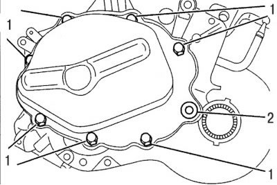
Pic. 5.33. Bolt location (1) mountings of the rear gearbox housing and plugs (2) oil level checks
- remove bolts 1 (pic. 5.33) and remove the rear cover from the gearbox housing;
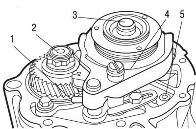
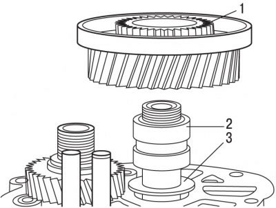
Pic. 5.27. Shift Fork Mount: 1 - cotter pin holding the gear shift fork; 2, 3 - nuts for fastening gears of the 5th gear; 4 - retaining ring; 5 - chute for oil supply
- Engage 5th gear and remove cotter pin 1 (pic. 5.27), holding the shift fork;
- put the transmission in neutral position, while the 5th gear fork should remain in place. Engage any other gear in order to block the gearbox shafts;
- remove the retaining ring 4;
- unscrew and remove the nuts securing the gears of the 5th gear;
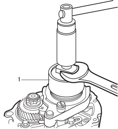
Pic. 5.28. Using the 0317-Y puller to remove the 5th gear hub
- using puller 0317-Y 1 (pic. 5.28) remove the 5th gear hub;
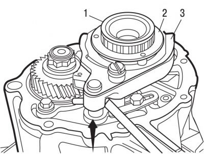
Pic. 5.29. Removing parts (direction shown by arrow): 1 - synchronizer hub; 2 - synchronizer; 3 - 5th gear engagement fork
- marker or paint mark the position of the synchronizer hub 1 (pic. 5.29) in relation to the synchronizer 2;
- remove as an assembly the synchronizer hub 1, the synchronizer 2 and the fork 3 for engaging the 5th gear;
Pic. 5.30. Removing the 5th gear: 1 - 5th gear drive gear; 2 - pressure ring; 3 - spacer
- remove the 5th gear 1 (pic. 5.30), pressure ring 2 and spacer 3;
Pic. 5.31. Secondary shaft fastening: 1 - fastening of the gearbox housing; 2 - locking bolts for fastening the secondary shaft bearing; 3 - axes of the reverse gear of the reverse gear; 4 - fixing the locking plate of the fork shaft
- unscrew the locking bolts 3 (pic. 5.31) fastenings of the bearing of a secondary shaft;
- unscrew the bolt 4 fastening the axis of the reverse gear of the reverse gear;
- remove the locking plate 2 from the fork shaft;
- turn out bolts 1 fastenings of a case of a transmission;
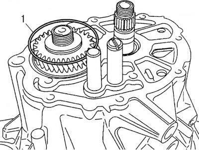
Pic. 5.32. Ring location (1) bearing fixation
- use special pliers or two pointed rods to remove ring 1 (pic. 5.32) bearing fixation. To facilitate the removal of the ring, lift the gearbox shaft;
- remove the gearbox housing. If necessary, use a wooden mallet to free the crankcase from the dowel sleeves.
To install the gearbox housing:
- apply sealing compound E15 to the mating surface of the clutch housing;
- install the gearbox housing;
- check that the oil supply chute 5 (see fig. 5.27) aligned with the hole in the gearbox housing;
- screw in bolts 1 (see fig. 5.31) fastenings of the gearbox housing and tighten them with a torque of 12.5 Nm;
- screw in the bolt 4 for fastening the axis of the reverse gear of the reverse gear and tighten it to a torque of 20 Nm;
- install the locking plate 2 of the fork axle in such a way that the flat part of the plate is located in the groove of the axle;
- install ring 1 (see fig. 5.32) into the bearing groove
- screw in bolts 3 (see fig. 5.31) mountings of the output shaft bearing and tighten them with a torque of 15 Nm;
- install spacer 3 (see fig. 5.30) so that the protrusion is located on the side of the bearing;
- install thrust bushing 2 and 5th gear pinion 1;
- install the 5th gear drive gear together with the synchronizer;
- simultaneously engage 3rd or 4th and 5th gears in order to block the gearbox shafts;
- unscrew the nut securing the input shaft of the gearbox. Apply locking compound E6 to the threads of the nut to prevent self-loosening;
- tighten the output shaft nut to 65 Nm and lock it by bending the metal plates so that they enter the splined grooves of the shaft;
- remove the 5th gear drive gear together with the synchronizer;
- set the 5th gear fork in the correct position;
- reinstall the 5th gear with synchronizer and fork. When installing, align the previously applied marks;
- install the retainer ball and drown it in the socket, pushing the clutch with the synchronizer;
- simultaneously engage 3rd or 4th and 5th gears in order to block the gearbox shafts;
- apply locking compound E6 to the threaded part of the input shaft;
- screw nut 3 (see fig. 5.27) on the input shaft, tighten it to 72.5 Nm and lock it;
- install a new cotter pin 1 holding the shift fork;
- apply sealing compound E15 to the mating surface of the rear crankcase;
- screw in, without tightening, plug 2 (see fig. 5.33) checking the oil level, while centering the crankcases;
- install the rear crankcase cover and secure with bolts 1, tightening them to a torque of 12.5 Nm;
- tighten the level check plug to 10 Nm;
- install the gearbox.