



- turn off the ignition and disconnect the ground wire from the battery;
- remove the crankcase ventilation system pipes;
- remove the air filter;
- disconnect and remove the air filter outlet pipe;
- remove the resonator;
- remove the decorative battery cover;
- remove the left front wheel arch mudguard;
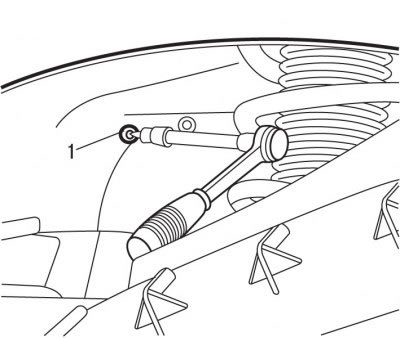
Figure 5.20. Unscrewing the bolt (1) securing the battery support
- unscrew bolt 1 from under the left front wheel arch (figure 5.20) battery support fastenings;
- remove the battery;
- remove the battery support;
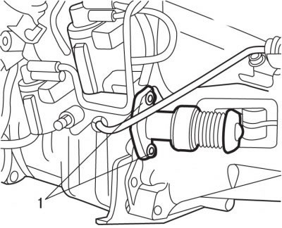
Figure 5.21. Location of bolts (1) for fastening the clutch slave cylinder
- unscrew bolts 4 (figure 5.21), remove the clutch slave cylinder 1 and attach it to the body with soft wire;
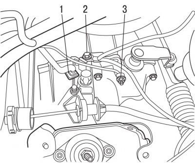
Figure 5.22. Electrical connector mounting location: 1 - bolt; 2 - nut; 3 - electrical connector
- unscrew bolt 1 (figure 5.22), nut 2 and disconnect electrical connector 3;
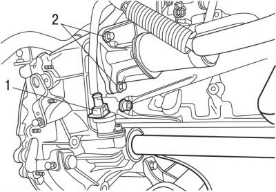
Figure 5.23. Location of electrical connector (1) and bolts (2)
- disconnect electrical connector 1 (figure 5.23), unscrew bolts 2;
- unscrew the lower bolts securing the clutch housing to the cylinder block;
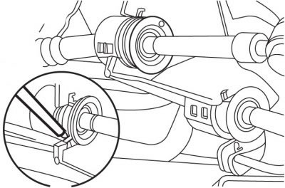
Figure 5.24. Using a screwdriver blade to push back metal tabs before disconnecting the transmission control rods
- using a screwdriver blade, press out the two metal tabs, disconnect the transmission control rods and move them away from the transmission support (figure 5.24);
- raise the car by lifting the front wheels;
- remove the drive shafts;
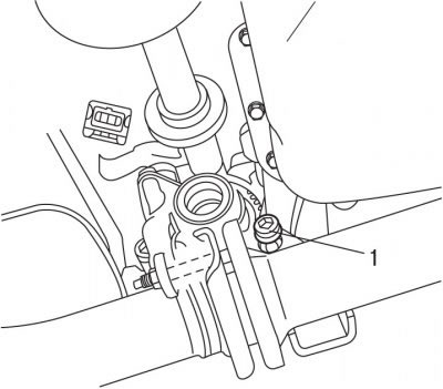
Figure 5.25. Location of bolt (1) above front exhaust pipe connection
- unscrew bolt 1 (figure 5.25), located above the front connection of the exhaust pipes;
- lower the car;
- remove the windshield wiper drive mechanism;
- install a support crossmember to support the power unit;
- hook the crossmember support clamp onto the engine lifting bracket;
- hook the lifting cable clamps to the gearbox;
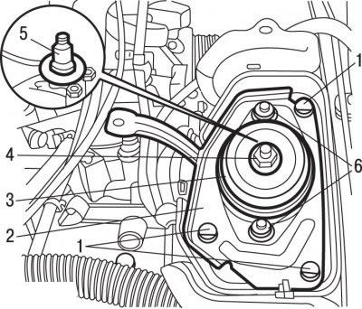
Figure 5.13. Fastening the elastic support: 1 - bolts; 2 - bracket; 3 - elastic support; 4 - nut, 65 Nm; 5 - gearbox axis; 6 - bolts, 30 Nm
- unscrew nut 4 (see Figure 5.13) fastening the gearbox suspension axle and remove it together with the washer;
- unscrew the 6 bolts securing the cushion;
- remove elastic pad 3;
- unscrew bolts 1 and remove bracket 2 of the gearbox axle;
- using a special bushing 0317-AB, remove the gearbox axle 5;
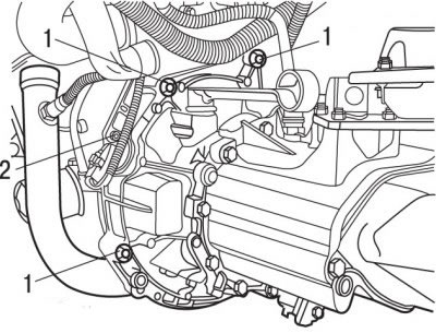
Figure 5.26. Location of gearbox mounting bolts (1) and speed sensor support (2)
- unscrew the upper bolts 1 (figure 5.26) gearbox mounts;
- unscrew the bolt and remove the support 2 of the speed sensor;
- remove the gearbox.
To install the gearbox:
- check the condition of the clutch;
- clean the splined portion of the gearbox input shaft;
Caution! Do not apply grease to the gearbox input shaft splines.
- check for oil leaks at the clutch release bearing level;
- check for oil leaks at the rear crankshaft sealing ring;
- check the wear of the clutch disc friction linings;
- replace the differential sealing rings, after lubricating the working edges of the rings;
- replace with new self-locking nuts and bolts, as well as lock washers and sealing gaskets;
Caution: Make sure that the engine block is fitted with guide bushings to centre the gearbox.
- lubricate the clutch release bearing guide bushing with a thin layer of special G12 grease. The lubricant layer must be thin and uniform, otherwise, when the clutch is operating, excess lubricant will be thrown onto the working surfaces of the clutch, which may impair its operation;
- attach the gearbox to the engine;
- move the gearbox towards the engine so that the input shaft of the gearbox enters the splines of the driven clutch disc (to align the splines of the gearbox input shaft with the splines of the clutch driven disc). This may require turning the engine crankshaft slightly. When installing the gearbox, the input shaft should not hang on the clutch disc;
- having moved the gearbox forward, install the clutch housing on the guide bushings of the cylinder block;
- using the special sleeve 0317-AB, install the axis 5 (see Figure 5.13) gearbox hangers together with the washer;
- install the 2 gearbox axle bracket and secure it with bolts 1;
- install elastic gasket 3;
- screw in bolts 6, tightening them by hand at this stage;
- install the washer and tighten the nut 4 securing the gearbox suspension axle;
- tighten bolts 6 to 30 Nm and nut 4 to 65 Nm;
(Original text is located at: PeugeotBook.ru)
Caution: Before tightening the elastic gasket mounting bolts, center the power unit.
- install the clutch slave cylinder and secure it with bolts;
- press and release the clutch pedal several times until it stops;
- install the drive shafts;
- fill the gearbox with oil;
- connect the ground wire to the battery;
- initialize all computers.